The project is an online platform for managing the transactions of room booking and reservation. It was designed and developed in PHP, MySQL and Bootstrap. This project was intended to cater multiple hotels, unlike other hotel management system that focuses only on a specific hotel. Through this study, it was realized that instead of making a system individually for every hotel, the researchers decided to develop a generic information system that caters the needs of every hotels. The said project functions the same with the usual hotel management system; it has a feature where customers can view and select a room for reservation, payment option is also available and in addition, the hotel managers can access the system to upload the information about their hotel room, amenities and other services. Rapid Application Development was used as a model for software development, with this type of model, a prototype of the system was created in the early stage of the project. The system undergoes several testing procedures such as the IT expert and the End-user acceptance testing. Results showed that the system has a high score in terms of accuracy, speed and efficiency, and therefore recommends for implementation.
Beneficiaries of the system/study
This study has no specific clientele since it is applicable to most of the hotel. But the output of the study may be beneficial to the following:
Hotel Managers and Owners – they don’t have to develop and maintain an information system since this project can almost cater the requirements that they want.
Customers – this is a one-stop shop for all customers, they will not anymore jump from one website to another just to look of available rooms.
Researchers – this will be a challenge for the developers to develop a system that will cater the needs of every hotel.
Future Researchers – for the next batch of researchers, this will serve as the guide to develop similar idea that implements a generic feature for another industry or field of study.
Screenshots of the project in no particular order
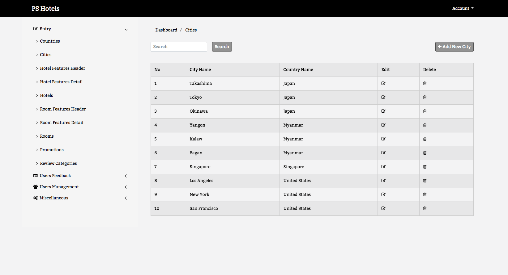
Image may be NSFW. Clik here to view.
Multi Hotel Management System City Management
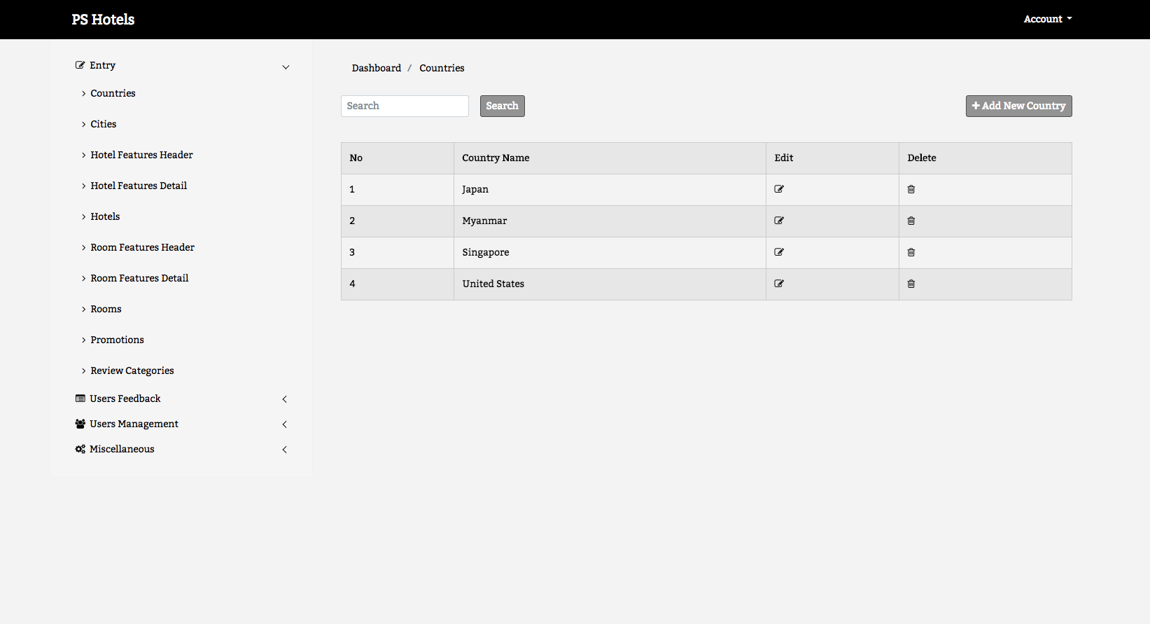
Image may be NSFW. Clik here to view.
Multi Hotel Management System Country Information Management
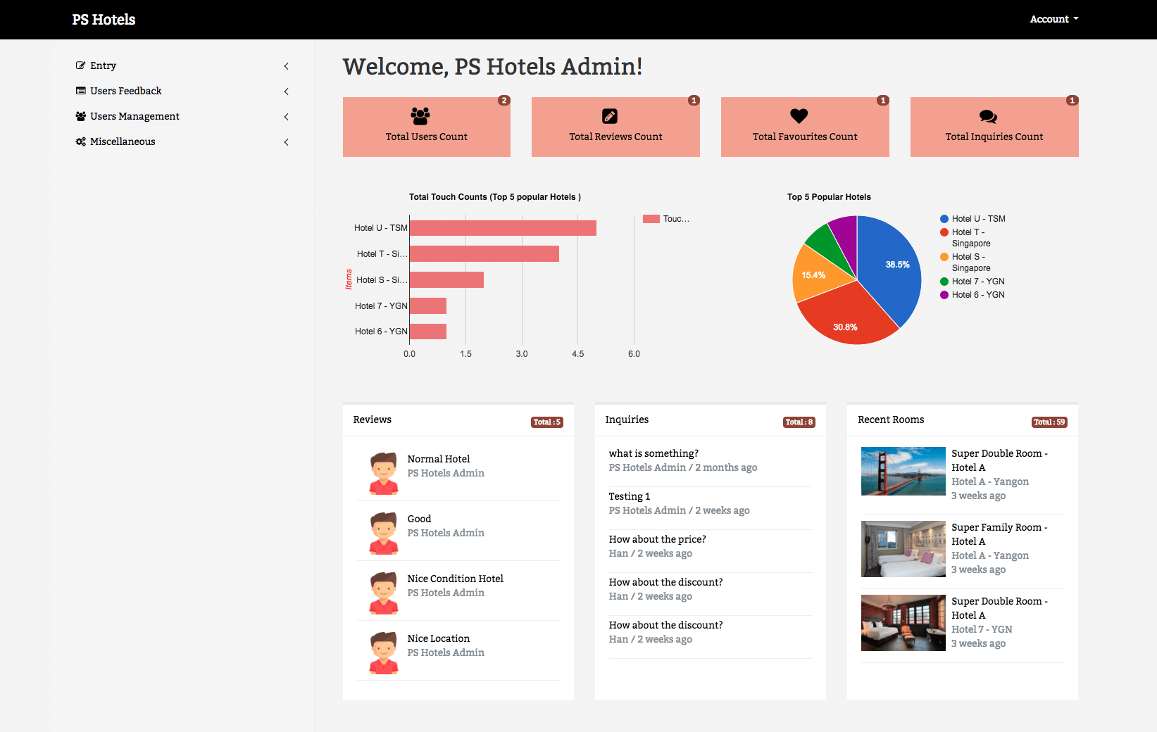
Image may be NSFW. Clik here to view.
Multi Hotel Management System Dashboard Module
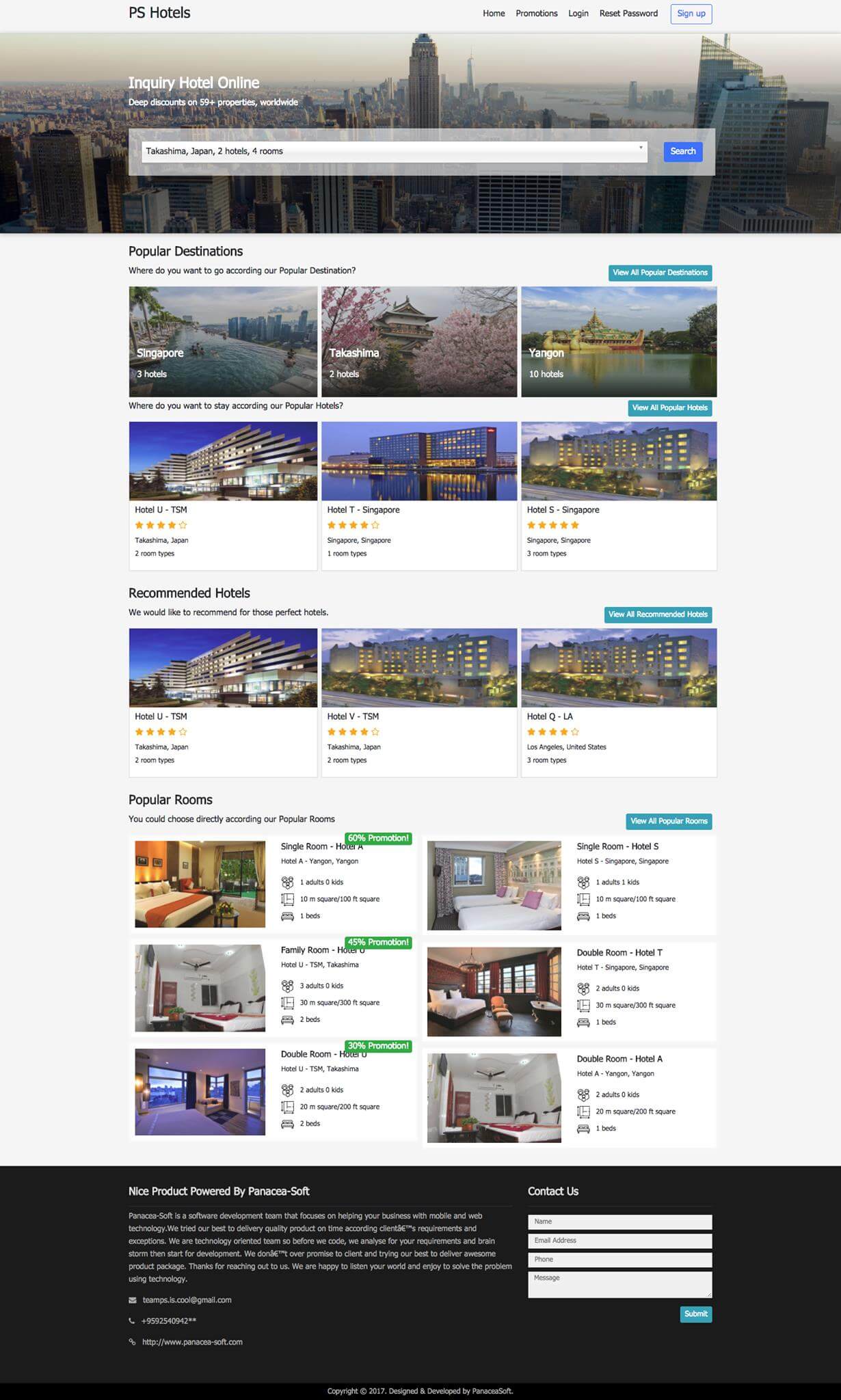
Image may be NSFW. Clik here to view.
Multi Hotel Management System Frontend Website
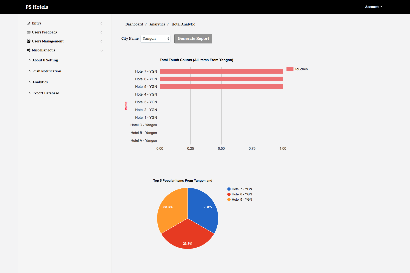
Image may be NSFW. Clik here to view.
Multi Hotel Management System Hotel Analytic Module
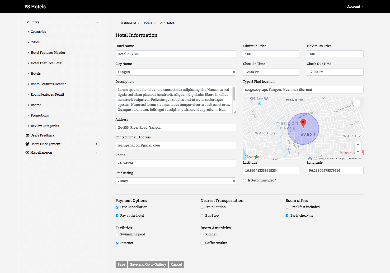
Image may be NSFW. Clik here to view.
Multi Hotel Management System Hotel Information Encoding
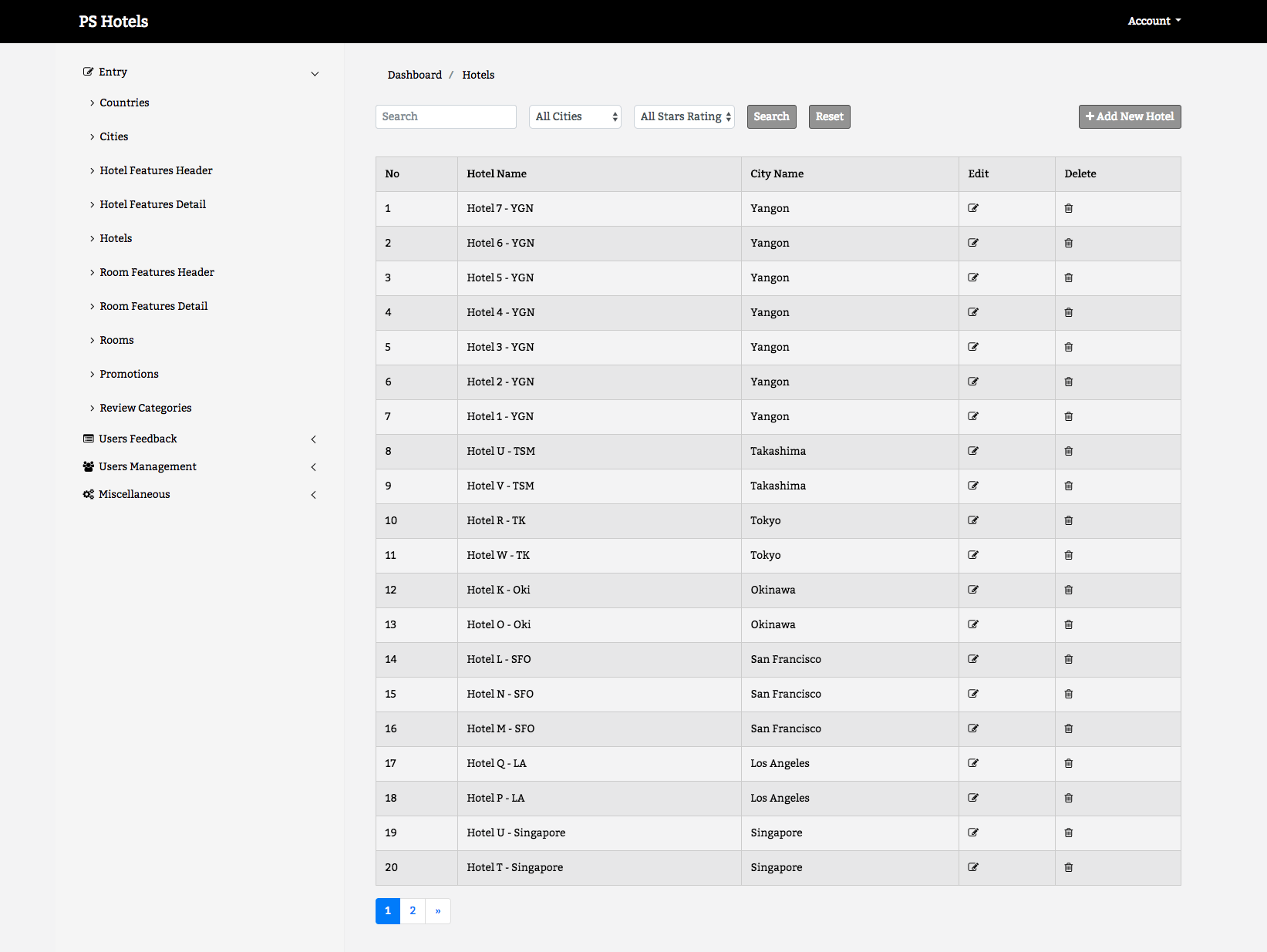
Image may be NSFW. Clik here to view.
Multi Hotel Management System Hotel Management Module
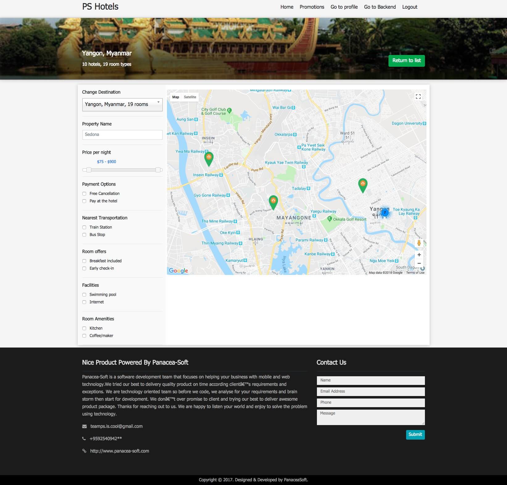
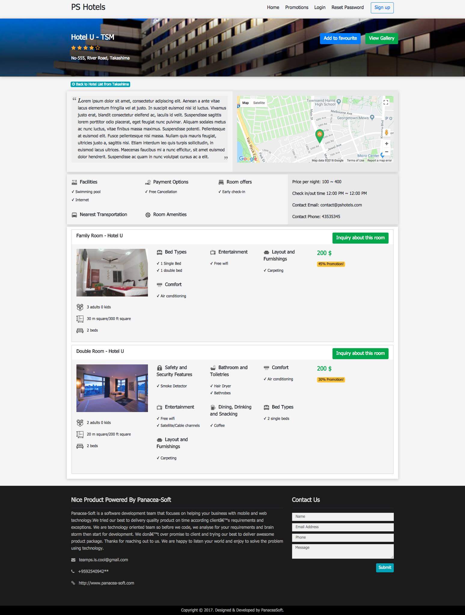
Image may be NSFW. Clik here to view.
Multi Hotel Management System Hotel Map Page
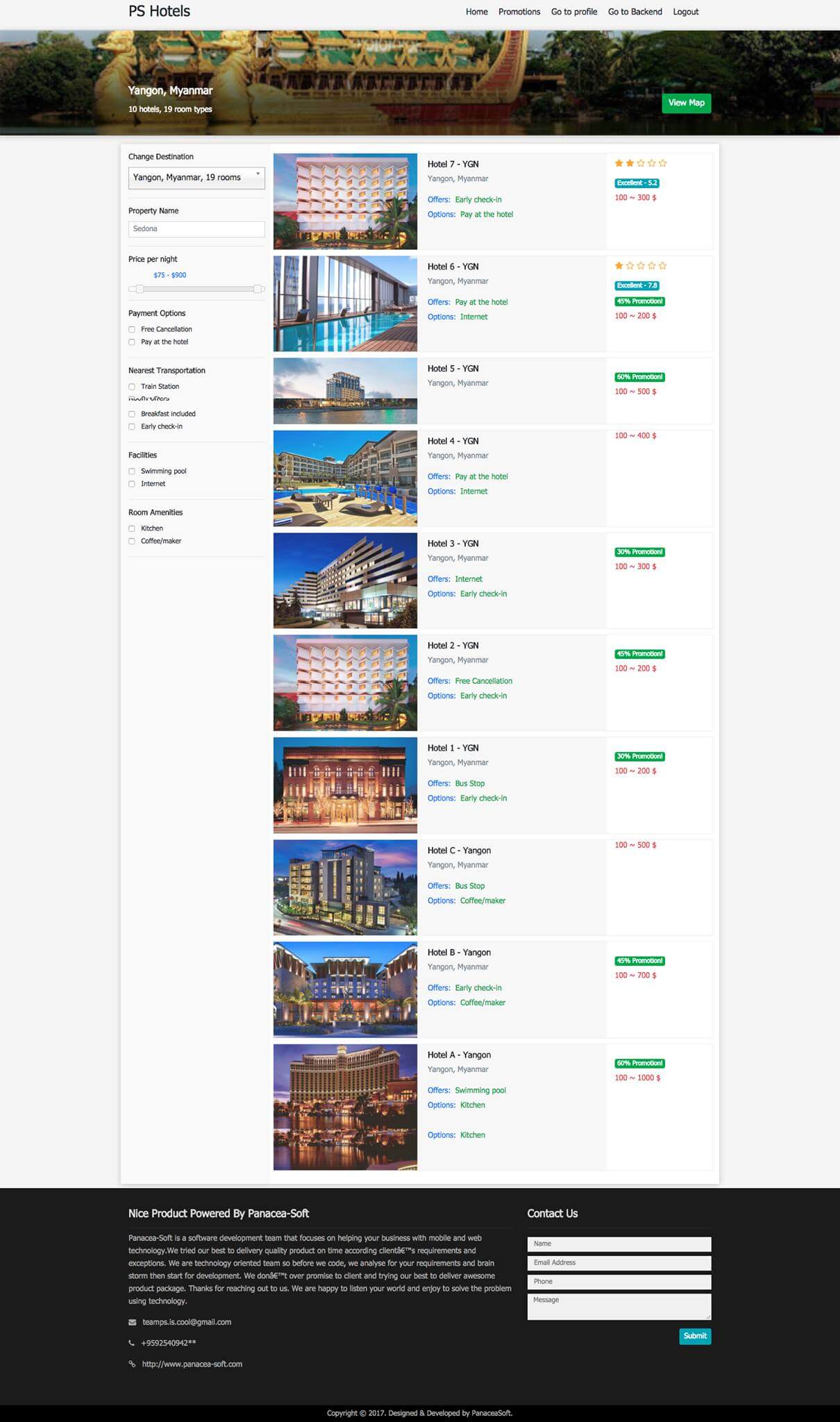
Image may be NSFW. Clik here to view.
Multi Hotel Management System Hotel Search Module
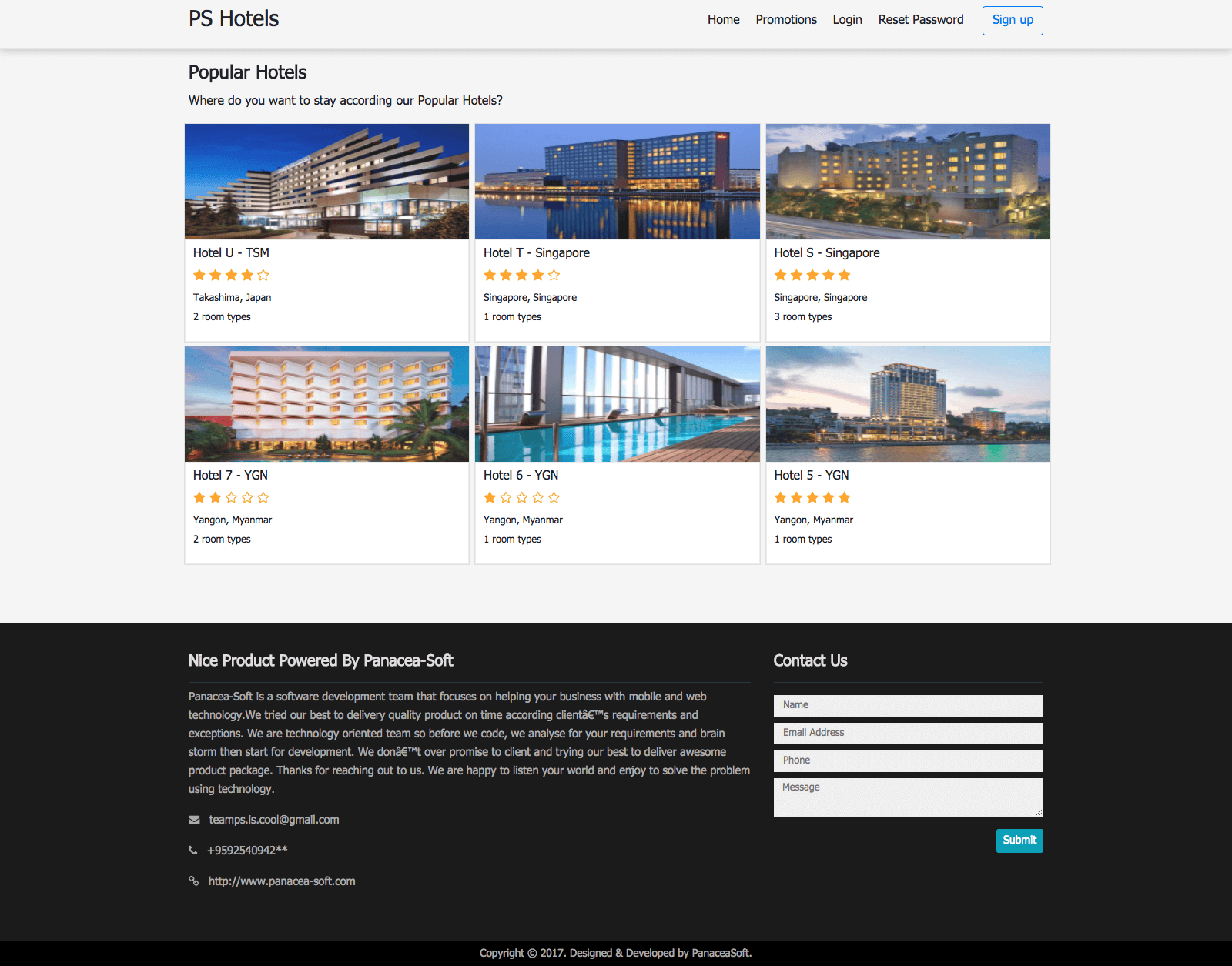
Image may be NSFW. Clik here to view.
Multi Hotel Management System Popular Hotel Page
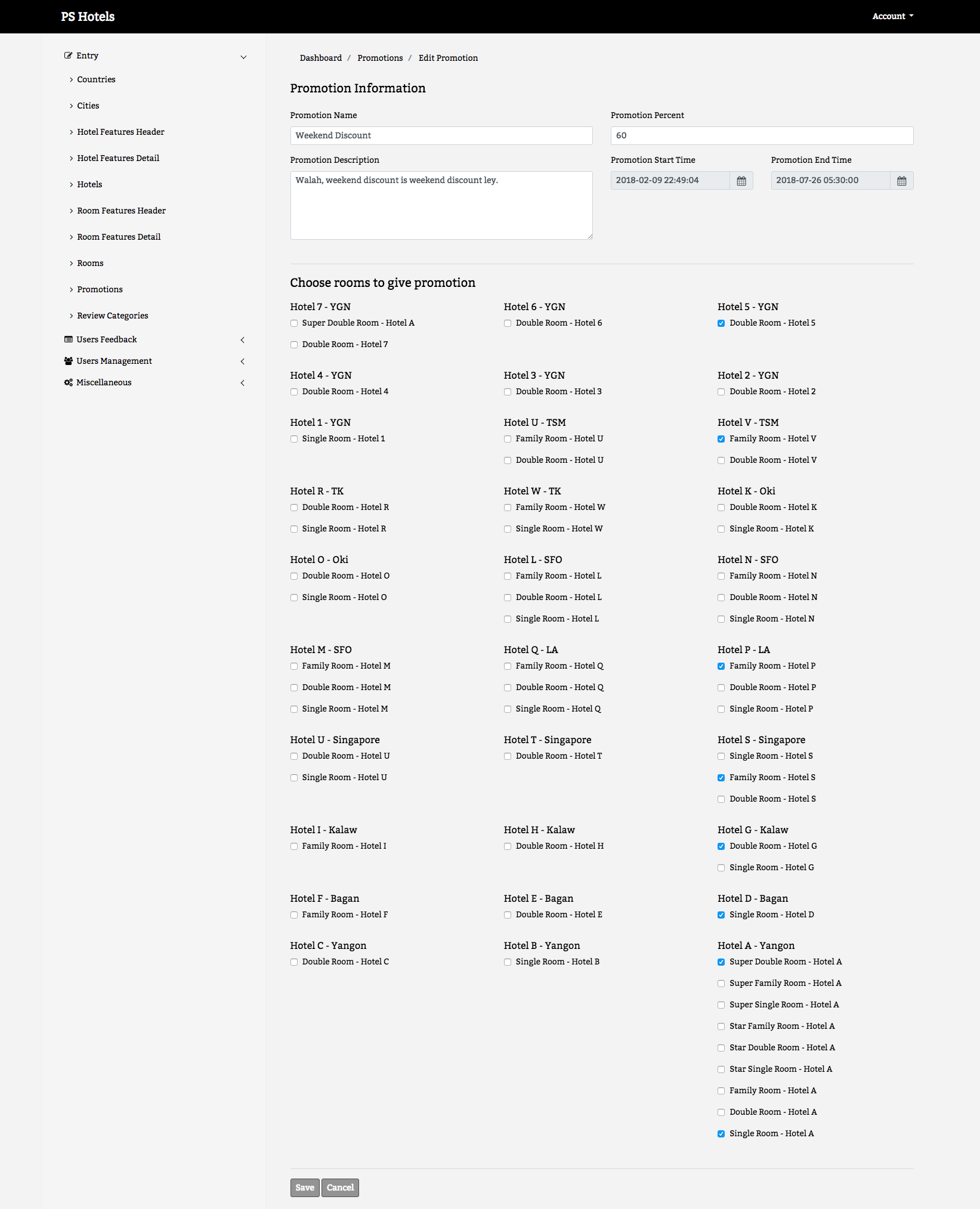
Image may be NSFW. Clik here to view.
Multi Hotel Management System Promotion Information
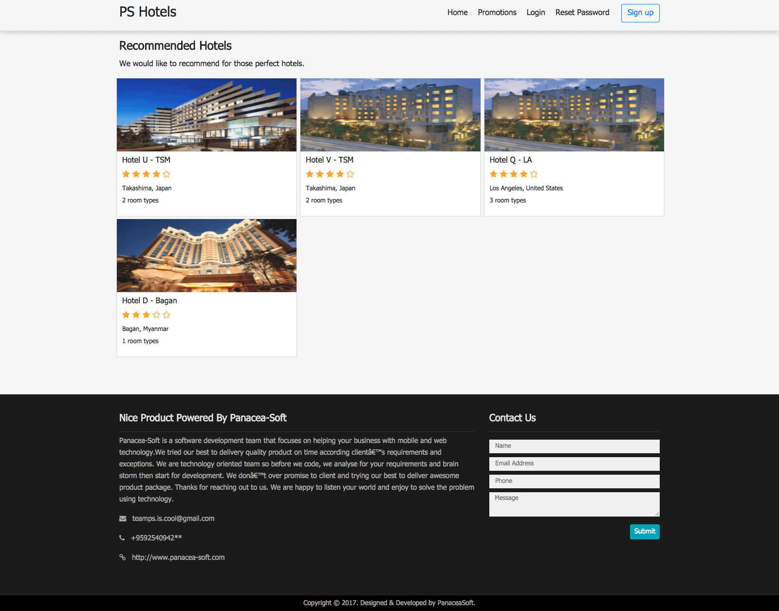
Image may be NSFW. Clik here to view.
Multi Hotel Management System Recommended Hotel Page
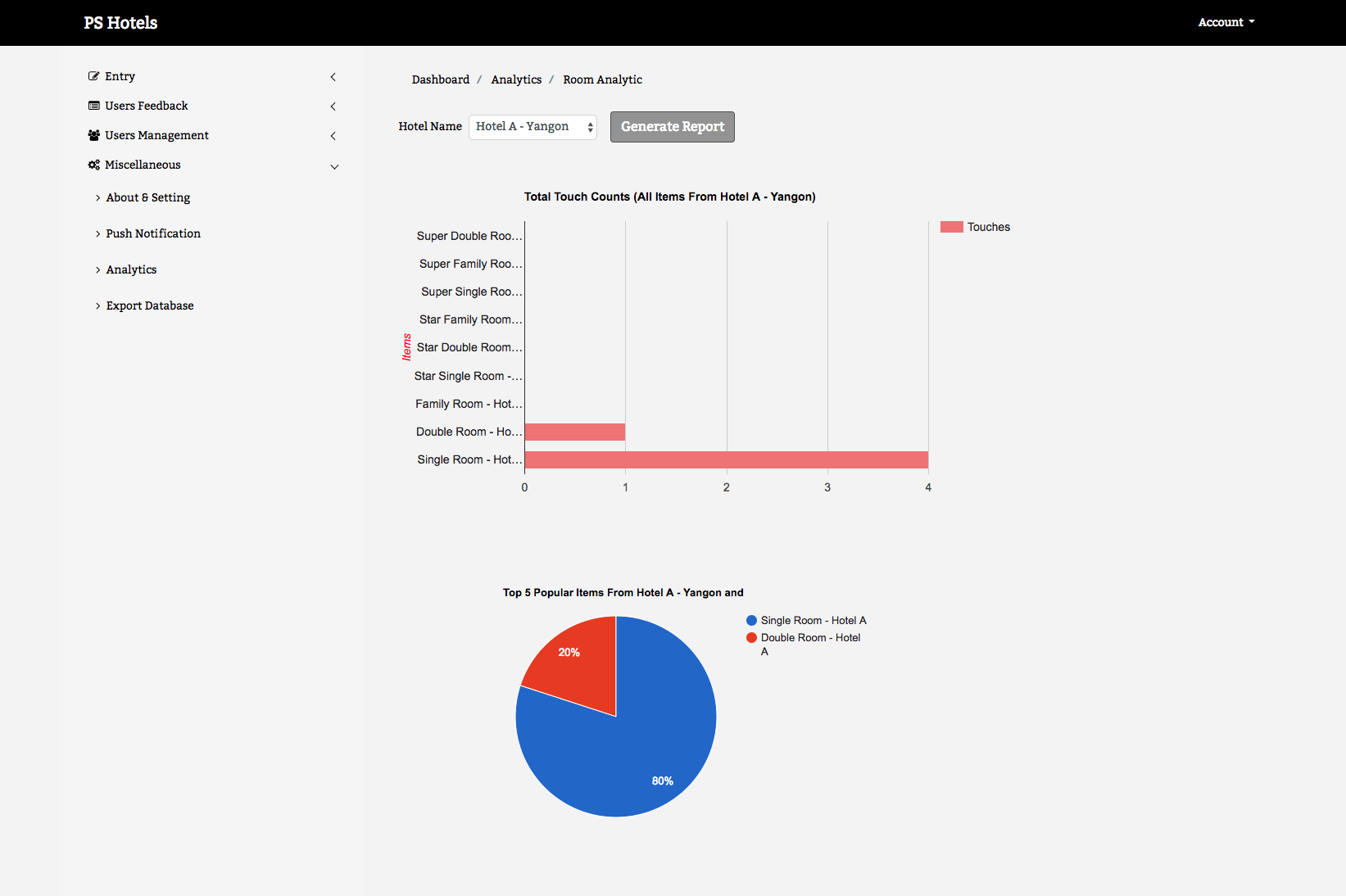
Image may be NSFW. Clik here to view.
Multi Hotel Management System Room Analytic
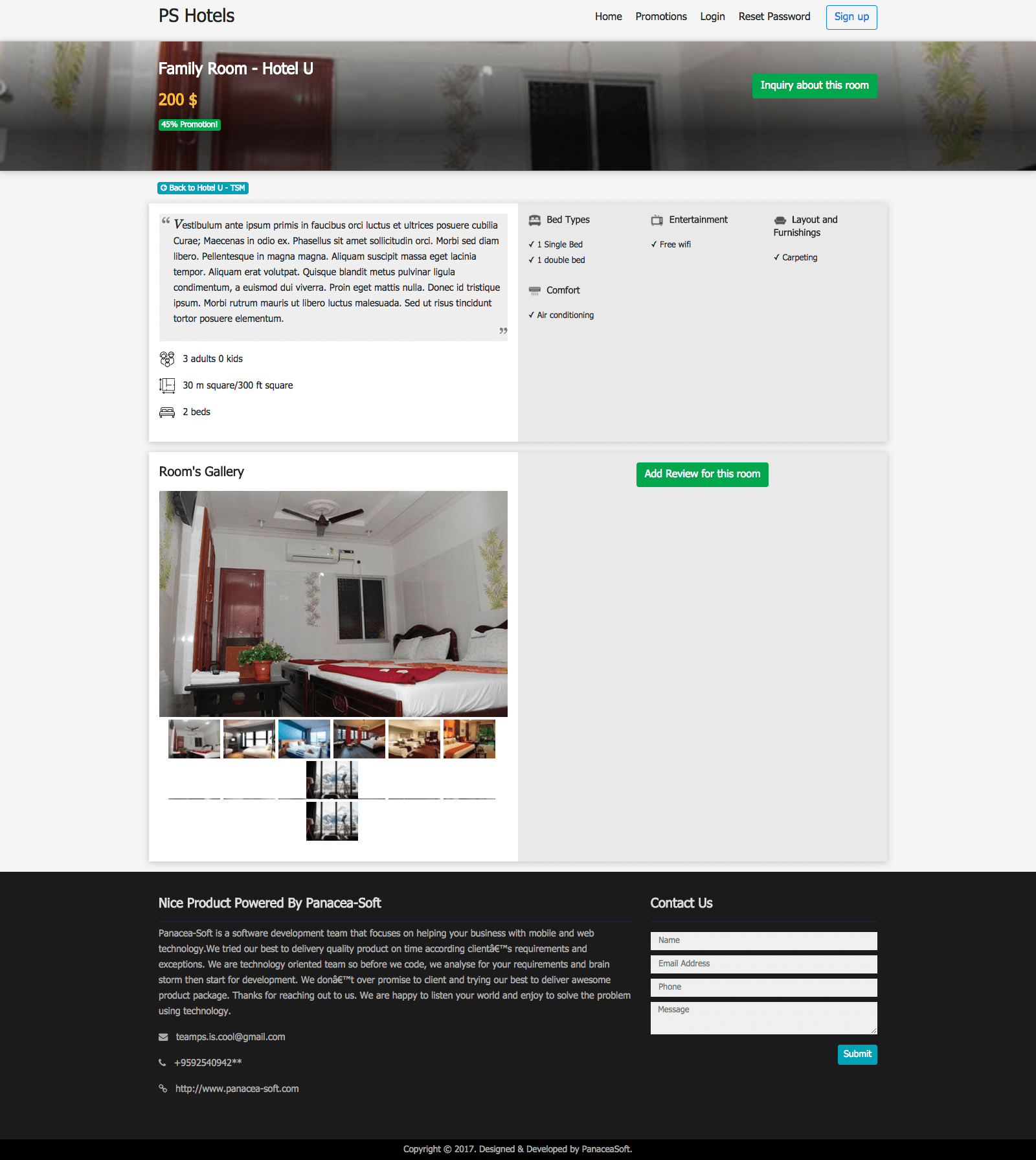
Image may be NSFW. Clik here to view.
Multi Hotel Management System Room Detials Page
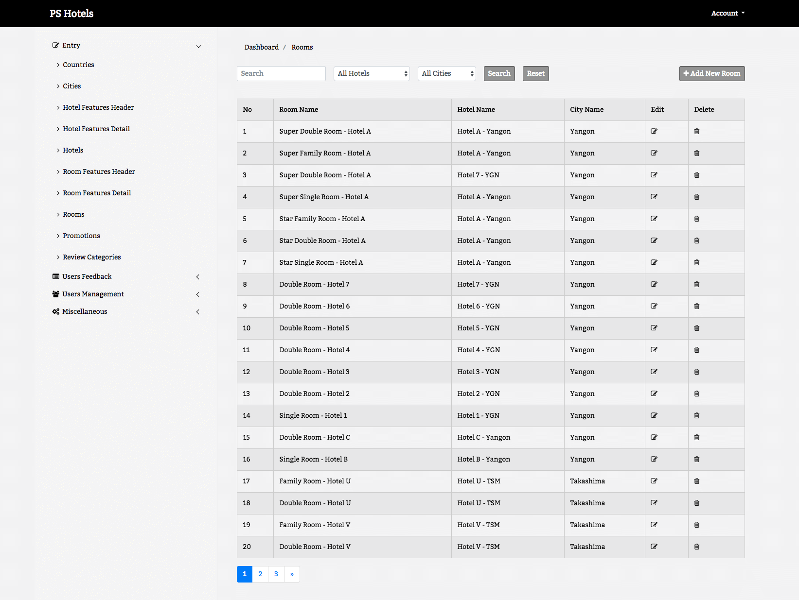
Image may be NSFW. Clik here to view.
Multi Hotel Management System Room Management
Image may be NSFW. Clik here to view.
Multi Hotel Management System Website
Development Tools
The Hypertext processor (PHP) is a programming language that allows web developers to create dynamic content that interacts with database (Taie, 2013). For this project, the PHP Code used is embedded into the HTML source codes which is linked to the database and then interpreted by a web server that generates the page document for proper understanding.
Structured Query Language (SQL) is a database programming language designed for managing and retrieving data. It specializes in updating, deleting and requesting information from database. SQL is used in this project to create database that stores user’s information (data). The benefits of SQL to this project are: it is easy to use, an open source and user friendly.
Hypertext Markup Language (HTML) and Cascading Styling sheet (CSS) are tools used in building Web pages. (Berners-Lee. 1998). HTML provides the structure of the web pages (for example headings and paragraphs). CSS is a language created to define and style the appearance of content and other materials of the Web page (Taylor, 2013) (for example fonts and size). The advantages of using HTML and CSS are: it has a build in function (easy to use) that allows users specify various format and style properties.
JavaScript: This is a dynamic programming language used as a part of web browser which allows client side script interact with user and server side. It is increasingly considered as an “assembly” language or the “x86 of the web”. (Eich, 1995). This scripting language is classified as a prototype-based language with dynamic typing which has a first-class function. (McFarland 2008).
Notepad++ is used in this project as the main source code editor needed in developing the system. It supports several languages, which makes it suitable for this project.
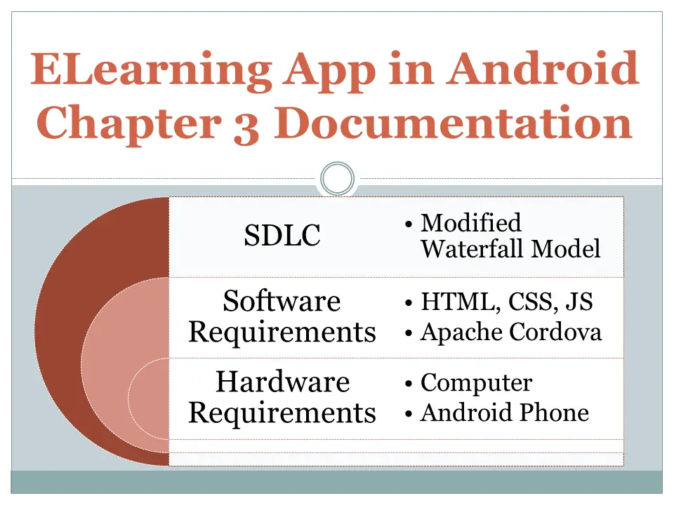
This document/article is all about the chapter 3 documentation of the capstone project entitled ELearning App in Android. The chapter 3 includes the technical background of the study which composed of the SDLC model used by the researchers, the development tools or the programming environment used in the development of the said study and the hardware requirements used in both development and implementation phase.
Image may be NSFW. Clik here to view.
ELearning App in Android Chapter 3 Documentation
TECHNICAL BACKGROUND
Software Development Life Cycle Model
The software development life cycle (SDLC) is the entire process of formal, logical steps taken to develop a software product. Within the broader context of Application Life cycle Management (ALM), the SDLC is basically the part of process in which coding/programming is applied to the problem being solved by the existing or planned application. The SDLC is broken down into six stages; project planning, requirements definition, design, development, integration/test, and application/acceptance. The relationship of each stage to the others can be roughly described as a waterfall, where the outputs from a specific stage serve as the initial inputs for the following stage. During each stage, additional information is gathered or developed, combined with the inputs, and used to produce the stage deliverables (Author: Michael L. Brown Jr.).
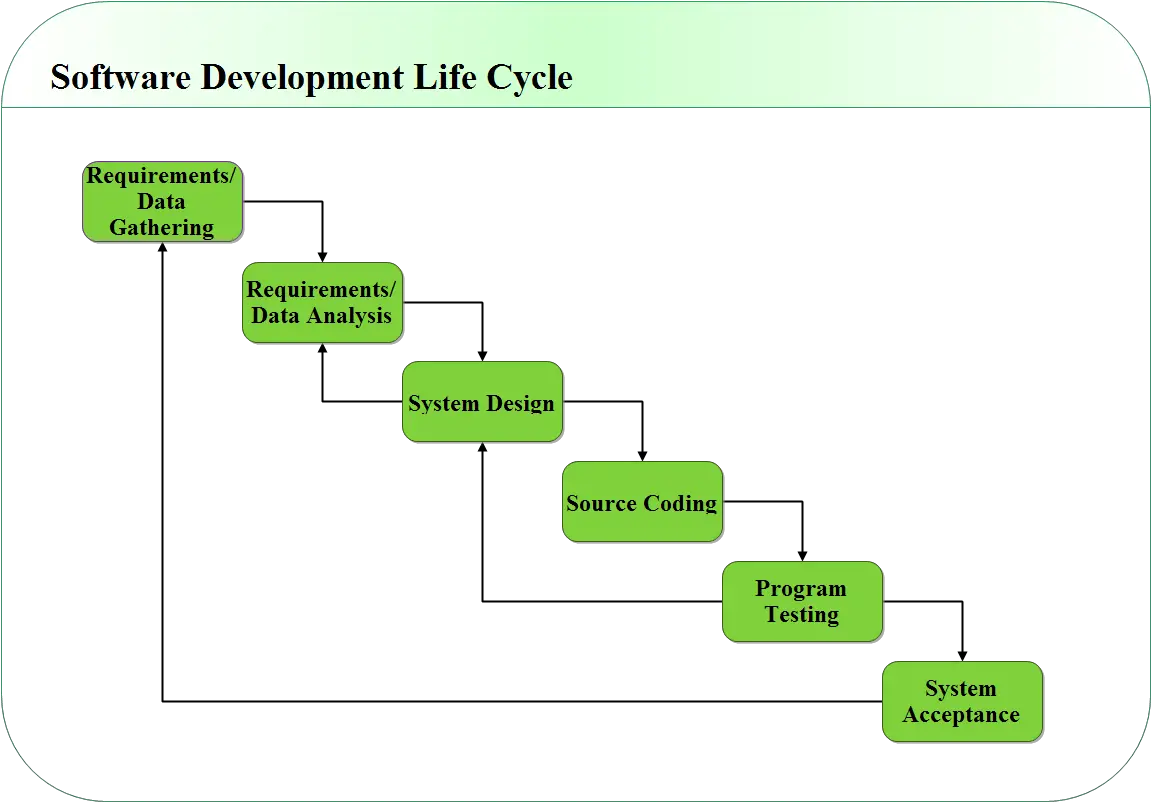
The researchers have chosen the Waterfall Approach Model. According to (Youssef Bassil, 2012) it includes six stages such as requirements/data gathering, requirements/data analysis, system design, source coding, and program testing and system acceptance. The waterfall Model illustrates the software development process in a linear sequential flow. This means that any phase in the development process begins only if the previous phase is complete. The waterfall approach does not define the process to go back to the previous phase to handle changes in requirement. Therefore, different projects may follow different approaches to handle such situations.
The researchers choose waterfall approach model because every application development follows a certain methodology. Waterfall SDLC is a sequential software development methodology to describe a process for planning, creating, testing, and deploying an information system. This is a process used by IT analysts in order to develop or redesign high quality software system which meets both the customer and the real world requirement taking into consideration all associated aspects of advantage and disadvantage of software testing, analysis and post process maintenance.
Image may be NSFW. Clik here to view.
ELearning App in Android Modified Waterfall Model
Figure 1.0Modified Waterfall Model
Software Requirements
The following is the list of software requirements used for development and implementation of the system.
Development
HTML, CSS, and JavaScript
HTML (Hypertext Markup Language) is the set of markup symbols or codes inserted in a file intended for display on a World Wide Web browser page. The markup tells the Web browser how to display a Web page’s words and images for the user.
CSS Stands for “Cascading Style Sheet.” Cascading style sheets are used to format the layout of Web pages. They can be used to define text styles, table sizes, and other aspects of Web pages that previously could only be defined in a page’s HTML.
JavaScript is a programming language commonly used in web development. It was originally developed by Netscape as a means to add dynamic and interactive elements to websites. While JavaScript is influenced by Java, the syntax is more similar to C and is based on ECMAScript, a scripting language developed by Sun Microsystems.
The researchers choose these platforms for developing an application for migration of web apps and cross-linking user interfaces that can be produced in spite of giving add-on features within our application. This is Primary programming language in creating this application.
Phone Gap
Phone Gap is a mobile development framework produced by Nit obi, purchased by Adobe Systems in 2011. It enables software programmers to build applications for mobile devices using JavaScript, HTML5, and CSS3. Because it allows you to create mobile apps using standardized web APIs for the platforms you like.
The researcher’s use this phone gap development using JavaScript, html5 and CSS3. It allows you to create mobile apps using standardized web API for the platforms you care about it.
Phone Gap Build
It’s a cloud service that allows you to quickly build mobile applications and easily compile them without SDKs, compilers and hardware.
The researchers choose this for the cloud service to get easy to compile without SDKs, compilers.
Apache Cordova
It’s a platform for building native mobile applications using HTML, CSS and JavaScript. This allows you to build mobile applications locally.
The researchers choose this because this allows a smartphone app to be developed with just HTML, CSS, and JavaScript.
Eclipse
It’s an integrated development environment (IDE). It contains a base workspace and an extensible plug-in system for customizing the environment. The researchers choose this because eclipse is the development of an environment that can be used to develop applications.
ADT Plugin
Android Development Tools (ADT) is a plugin for the Eclipse IDE that is designed to give you a powerful, integrated environment in which to build Android applications. The researchers will use this to developing in eclipse with this ADT because this ADT gives and incredible boost in developing Android Applications.
SDK (Software development kit)
The Android SDK provides you the API libraries and developer tools necessary to build, test, and debug apps for Android. The researchers will use this for developing and debugging tools using Android SDK.
Hardware Requirements
While Android is designed to support a wide variety of hardware the following is the list of hardware requirements used for the implementation of the system..
1.5 GHz dual core processor. A single processor has two processing cores. It can handle 2 threads at the same time and faster in multitasks. It can also switch threads rapidly if you have CPU-z you will find that the only difference in number of threads.
RAM: 512 MB(higher much better). It is the most important factor in mobile performance. The amount of RAM listed for each system above is estimated for normal usage like accessing the Internet, word processing, standard mobile applications and playing android games. It stores active programs and data, for
Symmetric multiprocessing. It can process programs by multiple processors that share a common operating system and memory. It allow any processor to work on any task no matter where the data for that task are located in memory, provided that each task in the system is not in execution on two or more processors at the same time.
Operating System: Android OS any Version (higher much better). This platform is needed to run the system to your mobile device. Higher version is much better.
Credits to the authors/developers of the project
You may visit our facebook page for more information, inquiries and comments.
K12 Grading System Methodology Chapter 4 Documentation
Chapter IV
METHODOLOGY
This article/documentation is an example capstone project that discusses the chapter 4 which is the methodology. The project entitled K12 Grading System used a modified waterfall model for the conduct of study and development of the system. This article will discuss and define the stages of the waterfall model and the steps conducted by the researchers, in addition, it also includes the software and hardware requirements for the development and implementation of the said capstone project.
Image may be NSFW. Clik here to view.
K12 Grading System Methodology Chapter 4 Documentation
Requirements Analysis
The requirements were gathered by the researchers from the end-user by conducting interview, observation, and consultation. The gathered data was used as basis in the design of the system. The researchers formulated a project plan and decided what features to integrate to the system which will minimize the problems encountered by the teachers and staff, improve efficiency and generate accurate reports.
Requirements Documentation
This section presents the methodology used to develop the system, the system’s functionality, the suggested system content by the teacher’s and the project plan in developing the said system. It also includes the software and hardware requirements, software developer and people ware recommendations.
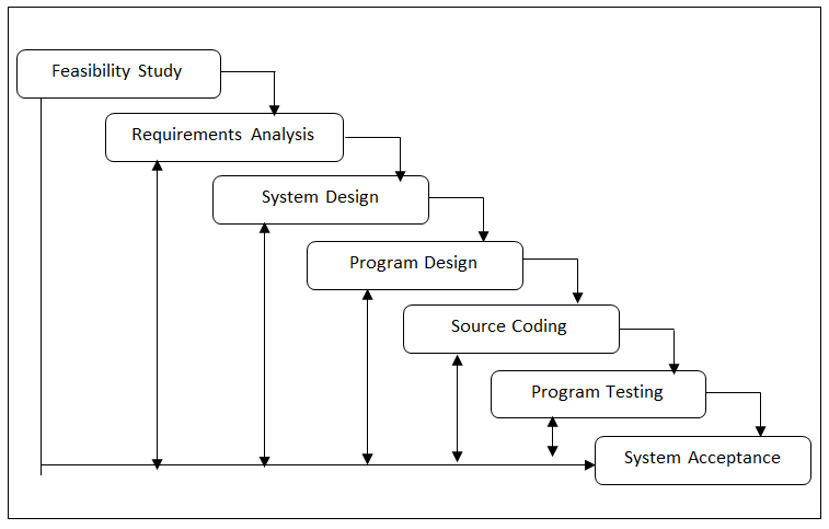
System Methodology – The researchers selected the Modified Waterfall Model for the development of the K12 Grading System. It is one of the process models in System Development Life Cycle (SDLC) that has a series of steps which involves the number of phases or procedures that gave the complete software. It is linear process where a sequential methodology is followed and the project progress is monitored and measured according to the completion of each phase.
Image may be NSFW. Clik here to view.
Modified Waterfall Model of K12 Grading System
Figure 1.0: The Modified Waterfall Model of K12 Grading System
The following are the phases involved in the development of the K12 Grading System as shown in Figure 1.0:
Feasibility Study – As the name implies, this phase is an analysis of the viability of an idea. The researchers tried to answer the essential question of “Should we proceed with the proposed project idea?” In order to answer the question, the researchers use principal tools like fact-gathering technique which basically includes surveys and interviews with the respondents. Surveys questionnaires were distributed and were calculated using the statistical analysis tools for a thorough and scientifically valid analysis of survey results. Cost-benefit analysis will be done that ascertains whether the benefits are worth the associated costs.
Requirements Analysis – In this most crucial phase of the project, the researchers established the system’s services, constraints and goals by consultation with user. They gather and list down all possible requirements of the system to be developed and then define it in manner that is understandable by both user and the developer; chalked out the functionality and limitations of the software. The data gathered or the requirement specifications served as the basis for the development of. Requirements were then analyzed and then proper documentation was prepared. This document was verified and endorsed to the client before starting the project.
System Design – In this phase, the system was designed based on the requirements needed in the system. The researchers utilized several analytical tools that can facilitate an understanding of how complex systems operate, how well they meet their overall goals. Process modeling and data modeling will be done to present the system’s data and the relationship between different data elements.
Source Coding – The system programmer create the source codes necessary for the system to be constructed; reviewed and revised the design of the tables and forms of the system, and tested the functionalities of the system.
Program Testing – This phase aimed to find out whether the software functions and features work according to the specification, ensure that the produced system is complete and performs efficiently, evaluate whether the software perform all activities after integration with the existing operating environment, and measure up the reliability and overall quality of the software.
System Acceptance – The units of the software are integrated together and a system is built. So we have complete software at hand which is tested to check if it meets the functional and performance requirements of the client. After testing is done, we will assemble the whole system and install it into the computer. For the proper installation of the system, one must take into consideration the hardware and software requirements. The supports were also provided at this stage. The client will be required to have user training for them to familiarize the system.
The researchers present the software development tools, hardware specifications, and people ware recommendations for the developed K12 Grading System.
Software Requirements
The following were the list of requirements of the software used during the development and implementation of the system.
Development
Visual Basic
Syncfusion Metro Studio
Net
PostgreSQL
Implementation
Windows Windows 7/8/10
Hardware Requirements
The following were the recommended lists of hardware for the development of the user interface of the developed system.
Processor: Pentium 4 or later
RAM: 512mb up
Hard Disk Space: 5gb up
People Requirements
The project proponents and the recommendation of appropriate users for the new system with specific task given are:
End-Users – required the end-user specifically the Faculty to be knowledgeable of the system, understands the program and its application. He or She should be a computer-literate, knows how to operate the system and is willing to undergo training.
Project Proponents – Supervises and monitors the entire project activities and its development; responsible for researching, planning and recommending software and system choices to meet an organizations business requirements; creates the source codes for the development of the system and must be expert with the programming language to be used in the development of the system.
Project Plan. Before the software project is implemented, the researchers prepared a project schedule that will list all the activities to be accomplished in the development of K12 Grading System.
Software Design and Development
This section includes the system functionalities to define what functions are to be included in the developed system to satisfy the needs of the teachers in the grading system and students pro Development and Testing
Now that we have system design, code generation begins. Code generation is conversion of design into machine-readable form. If designing of software and system is done well, code generation can be done easily. We will apply the information gathered in the first two phases to create the actual working parts of the system. We will then implement the program as designed in the earlier stages. In this phase, we will conduct unit testing, to ensure that there are no defects.
TESTING
These include initial testing and final testing of the K12 Grading System:
Initial Testing
In this phase, a series of unit testing were performed to check if the specification has been met and to look for any possible problems that may arise during implementation and operation of the software. In the evaluation of the K12 Grading System, the developers used the McCall’s Software Quality Model for the assurance of the evaluation by the three software experts. With the aid of this testing tool, we were able to assess whether the system functioned well or whether it needs improvements.
Final Testing
In this phase, a self-made testing tool was used in measuring the final testing. The said testing instrument was composed of two parts. Part I is for the profile of the respondents and Part II is for the User’s Evaluation Form. The responses for the functions/features will be rated on this manner; 5-Excellent, 4-Very good, 3-Good, 2-Fair, 1-Poor. The final testing will be evaluated by the end-user for them to check the features of the function of the system. The number of respondents was calculated using the Slovins formula. In order to meet the expectation of the end user, the system should work accurately and accordingly.
Validity of the Final Testing Instrument
The developers presented the self-made testing instrument to the evaluators or experts to check its conformance to standard for validation purposes. The expert rated it in terms of accuracy that referred to the precision of computations and control. The validity referred to the degree to which a particular instrument is useful in measuring that which it is designed to measure according to Carter V. Good and Douglas F. Scates.
Implementation Result
After a series of analysis and computations, the results of the evaluation for initial and final testing were presented. The developed system was evaluated by three IT experts during the initial testing using the Software Quality Model based on the criteria set forth by McCall’s and the end-users during the final testing using the validated self-made testing tool. Having an overall weighted mean of 4.10(Good) and 4.48(Excellent) for initial and final testing respectively, it only showed that the K12 Grading System meets the requirements of our clientele.
Credits to the authors/developers of the project
You may visit our facebook page for more information, inquiries and comments.
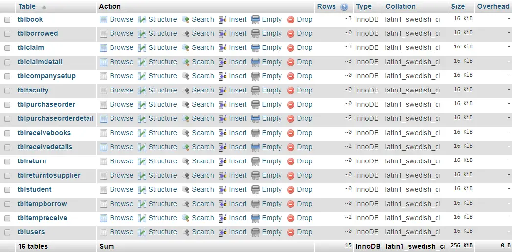
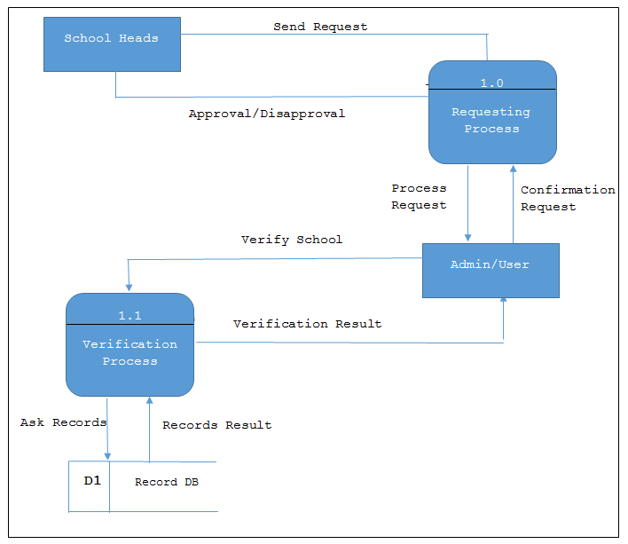
Library Resources Management System Database Design
This article will provide you with the list of tables and entities for every table for the library resources management system. This is a hybrid library system for it includes the processing of book purchase, delivery details and as well as the claiming of books ordered by the students and faculty.
Image may be NSFW. Clik here to view.
Library Resources Management System Database Design
tblbook – this table will store the information of the book as presented below and it has 8 attributes.
id – this is the primary key of the table, primary key refers to the unique key which has no duplicate value.
This value is unique for every book in the library even if the book are identical
bookname – the title of the book will store under the field name bookname.
authors – the authors of the book will be stored in this column.
isbn – The International Standard Book Number is a numeric commercial book identifier which is intended to be unique. Publishers purchase ISBNs from an affiliate of the International ISBN Agency. An ISBN is assigned to each separate edition and variation of a publication. (https://en.wikipedia.org/wiki/International_Standard_Book_Number)
price – price column refers to the amount of the book from the supplier where it was purchased.
initialqty – for inventory purposes the initialqty is the column that stores the number of copies of the book.
gradelevel – this column represents the grade level (elementary, highschool, college) of who will be prioritized in the borrowing of a certain book. Example, if the book was bought for the need of grade 6 students then the grade 6 students will be on the priority list, but anyone can borrow the book.
Create SQL Statement – the statement below is used to create the tblbook, copy the sql statement and paste it in the sql manager/tab of your phpmyadmin.
CREATE TABLE IF NOT EXISTS `tblbook` (
`id` int(11) NOT NULL AUTO_INCREMENT,
`accessionnumber` varchar(11) NOT NULL,
`bookname` varchar(100) NOT NULL,
`authors` varchar(100) NOT NULL,
`isbn` varchar(20) NOT NULL,
`price` double NOT NULL,
`initialqty` int(11) NOT NULL,
`gradelevel` varchar(15) NOT NULL,
PRIMARY KEY (`id`)
) ENGINE=InnoDB DEFAULT CHARSET=latin1;
tblborrowed – list of books borrowed by the students, faculty and staff of the school will be recorded and archived in this table. The table has 8 columns.
id – this is the primary key of the table.
facultyid – foreign key that links to the primary key of faculty table (tblfaculty).
bookid – foreign key that links to the primary key of book table (tblbook).
qty – this column refers to the quantity of books borrowed.
daterecorded – date of transaction are stored in this column.
processedby – this column refers to the user who processed the transaction. This is a foreign key that connects to the user table (tbluser).
status – this field represents if the book has been returned or not. The values stored for this column is 0 and 1, 0 if returned, 1 for unreturned books.
duedate – this is the date that the book must be returned by the borrower.
Create SQL Statement – the statement below is used to create the tblborrowed, copy the sql statement and paste it in the sql manager/tab of your phpmyadmin.
CREATE TABLE IF NOT EXISTS `tblborrowed` (
`id` int(11) NOT NULL,
`facultyid` int(11) NOT NULL,
`bookid` int(11) NOT NULL,
`qty` int(11) NOT NULL,
`daterecorded` varchar(15) NOT NULL,
`processedby` int(11) NOT NULL,
`mstatus` varchar(11) NOT NULL,
`duedate` varchar(15) NOT NULL
) ENGINE=InnoDB DEFAULT CHARSET=latin1;
tblclaim – claim table will store the record on the books claimed by the students and faculty.
id – primary key of the table
studentid – foreign key of the table that connects to the student table (tblstudent).
daterecorded – this column represents to the date the book was claimed by the student.
total – total is the column for the total amount of claimed books.
processedby – this column refers to the user who processed the transaction. This is a foreign key that connects to the user table (tbluser).
Create SQL Statement – the statement below is used to create the tblclaim, copy the sql statement and paste it in the sql manager/tab of your phpmyadmin.
CREATE TABLE IF NOT EXISTS `tblclaim` (
`id` int(11) NOT NULL AUTO_INCREMENT,
`studentid` int(11) NOT NULL,
`daterecorded` varchar(15) NOT NULL,
`total` double NOT NULL,
`processedby` int(11) NOT NULL,
PRIMARY KEY (`id`)
) ENGINE=InnoDB DEFAULT CHARSET=latin1;
tblclaimdetail – this table is connected to the tblclaim table, since the student can claim more than one book, this table was created for that purpose.
claimid – this column contains the value of the id of the tblclaim
bookid – this is the foreign key that links to the book table (tblbook). It represents the book claimed by the student.
Create SQL Statement – the statement below is used to create the tblclaimdetail, copy the sql statement and paste it in the sql manager/tab of your phpmyadmin.
CREATE TABLE IF NOT EXISTS `tblclaimdetail` (
`claimid` int(11) NOT NULL,
`bookid` int(11) NOT NULL
) ENGINE=InnoDB DEFAULT CHARSET=latin1;
tblcompanysetup – this the table is used to store the information of the company or school. The values of this table will be used in every reports of the system.
id – primary key of the table.
companyname – name of the school or company.
address – school address.
contact – contact information of the school.
Create SQL Statement – the statement below is used to create the tblcompanysetup, copy the sql statement and paste it in the sql manager/tab of your phpmyadmin.
CREATE TABLE IF NOT EXISTS `tblcompanysetup` (
`id` int(11) NOT NULL,
`companyname` varchar(50) NOT NULL,
`address` varchar(100) NOT NULL,
`contact` varchar(15) NOT NULL
) ENGINE=InnoDB DEFAULT CHARSET=latin1;
tblfaculty – personal information of the faculty will be stored in the tblfaculty table and it has 6 entities.
id – primary key of the table.
facultyid – this is the id number provided the school for every faculty.
lastname – last name of the faculty.
firstname – first name of the faculty.
middlename – middle name of the faculty.
contact – contact information of the faculty.
Create SQL Statement – the statement below is used to create the tblfaculty, copy the sql statement and paste it in the sql manager/tab of your phpmyadmin.
CREATE TABLE IF NOT EXISTS `tblfaculty` (
`id` int(11) NOT NULL AUTO_INCREMENT,
`facultyid` varchar(15) NOT NULL,
`lastname` varchar(20) NOT NULL,
`firstname` varchar(20) NOT NULL,
`middlename` varchar(20) NOT NULL,
`contact` varchar(15) NOT NULL,
PRIMARY KEY (`id`)
) ENGINE=InnoDB DEFAULT CHARSET=latin1;
tblpurchaseorder – list of books that the library needs based on the request of the students and faculty will be recorded in the tblpurchaseorder and tblpurchaseorderdetail table.
id – the primary key of the table.
pono – this column is the purchase order number, it is a system generated value.
daterecorded – the date the purchase order was created and printed.
supplier – the name of the supplier where the books will be ordered.
processedby – this column refers to the user who processed the transaction. This is a foreign key that connects to the user table (tbluser).
Create SQL Statement – the statement below is used to create the tblpurchaseorder, copy the sql statement and paste it in the sql manager/tab of your phpmyadmin.
CREATE TABLE IF NOT EXISTS `tblpurchaseorder` (
`id` int(11) NOT NULL AUTO_INCREMENT,
`pono` varchar(15) NOT NULL,
`daterecorded` date NOT NULL,
`supplier` varchar(25) NOT NULL,
`processedby` int(11) NOT NULL,
PRIMARY KEY (`id`)
) ENGINE=InnoDB DEFAULT CHARSET=latin1;
tblpurchaseorderdetail – details of the purchase order are stored in this table.
poid – this column refers to the primary key of the tblpurchaseorder which is the id column.
bookid – foreign key that links to the primary key of book table (tblbook).
qty – quantity of books to be ordered
amount – the amount of book
total – total is equals to the qty * amount. This is optional, meaning you can omit this value since it is a derived attribute.
Create SQL Statement – the statement below is used to create the tblpurchaseorderdetail, copy the sql statement and paste it in the sql manager/tab of your phpmyadmin.
CREATE TABLE IF NOT EXISTS `tblpurchaseorderdetail` (
`poid` int(11) NOT NULL,
`bookid` int(11) NOT NULL,
`qty` int(11) NOT NULL,
`amount` float NOT NULL,
`total` float NOT NULL
) ENGINE=InnoDB DEFAULT CHARSET=latin1;
tblreceivebooks – list of books delivered by the supplier will be stored in the tblreceivebooks and tblreceivedetails.
id – primary key of the table
daterecorded – date of delivery
supplier – name of supplier
poid – reference id based on the purchase record. This is a foreign key that connects to the purchase table (tblpurchase)
processedby – this column refers to the user who processed the transaction. This is a foreign key that connects to the user table (tbluser).
Create SQL Statement – the statement below is used to create the tblreceivebooks, copy the sql statement and paste it in the sql manager/tab of your phpmyadmin.
CREATE TABLE IF NOT EXISTS `tblreceivebooks` (
`id` int(11) NOT NULL AUTO_INCREMENT,
`receiveno` varchar(11) NOT NULL,
`daterecorded` date NOT NULL,
`supplier` varchar(30) NOT NULL,
`poid` int(11) NOT NULL,
`processedby` int(11) NOT NULL,
PRIMARY KEY (`id`)
) ENGINE=InnoDB DEFAULT CHARSET=latin1 ;
tblreceivedetails – details of the delivery will be stored in this table.
receivedid – this value is the same to the value of the primary key of tblreceivebooks.
bookid – foreign key that links to the primary key of book table (tblbook).
qty – quantity of books received.
amount – the amount of book
total – total is equals to the qty * amount. This is optional, meaning you can omit this value since it is a derived attribute.
Create SQL Statement – the statement below is used to create the tblreceivedetails, copy the sql statement and paste it in the sql manager/tab of your phpmyadmin.
CREATE TABLE IF NOT EXISTS `tblreceivedetails` (
`id` int(11) NOT NULL AUTO_INCREMENT,
`receivedid` int(11) NOT NULL,
`bookid` int(11) NOT NULL,
`qty` int(11) NOT NULL,
`bamount` varchar(11) NOT NULL,
`btotal` varchar(11) NOT NULL,
PRIMARY KEY (`id`)
) ENGINE=InnoDB DEFAULT CHARSET=latin1;
tblreturn – there are cases that the book will be returned by the student or faculty, and to cater those scenario the tblreturn table will be created.
id – primary key of the table
facultyid – foreign key of the table that connects to the faculty table (tblfaculty).
bookid – foreign key that links to the primary key of book table (tblbook). This is the book that will be returned.
qty – number of books to be returned.
datereturned – date of transaction.
Processedby – this column refers to the user who processed the transaction. This is a foreign key that connects to the user table (tbluser).
Create SQL Statement – the statement below is used to create the tblreturn, copy the sql statement and paste it in the sql manager/tab of your phpmyadmin.
CREATE TABLE IF NOT EXISTS `tblreturn` (
`id` int(11) NOT NULL AUTO_INCREMENT,
`facultyid` int(11) NOT NULL,
`bookid` int(11) NOT NULL,
`qty` int(11) NOT NULL,
`datereturned` date NOT NULL,
`processedby` int(11) NOT NULL,
PRIMARY KEY (`id`)
) ENGINE=InnoDB DEFAULT CHARSET=latin1;
tblreturntosupplier – if the books delivered by the supplier is not the book needed by the school or it is not the book that reflects to the purchase order then the books will be returned to the supplier. Those records and transactions are also being recorded in the system.
id – primary key of the table.
bookid – foreign key that links to the primary key of book table (tblbook). This is the book that will be returned.
qty – quantity of books to be returned.
supplier – name of supplier
datereturned – date of transaction.
Processedby – this column refers to the user who processed the transaction. This is a foreign key that connects to the user table (tbluser).
Create SQL Statement – the statement below is used to create the tblreturntosupplier, copy the sql statement and paste it in the sql manager/tab of your phpmyadmin.
CREATE TABLE IF NOT EXISTS `tblreturntosupplier` (
`id` int(11) NOT NULL AUTO_INCREMENT,
`bookid` int(11) NOT NULL,
`qty` int(11) NOT NULL,
`supplier` varchar(30) NOT NULL,
`daterecorded` date NOT NULL,
`processedby` int(11) NOT NULL,
PRIMARY KEY (`id`)
) ENGINE=InnoDB DEFAULT CHARSET=latin1 AUTO_INCREMENT=1 ;
tblstudent – information of the students will be stored in the tblstudent table.
id – primary key of the table
studentidno – student id number provided by the school.
lastname – last name of the student.
firstname – first name of the student.
middlename – middle name of the student.
contact – contact information of the student,
gradelevel – grade level of the student.
Create SQL Statement – the statement below is used to create the tblstudent, copy the sql statement and paste it in the sql manager/tab of your phpmyadmin.
CREATE TABLE IF NOT EXISTS `tblstudent` (
`id` int(11) NOT NULL AUTO_INCREMENT,
`studentidno` varchar(11) NOT NULL,
`lastname` varchar(20) NOT NULL,
`firstname` varchar(20) NOT NULL,
`middlename` varchar(20) NOT NULL,
`contact` varchar(15) NOT NULL,
`gradelevel` varchar(15) NOT NULL,
PRIMARY KEY (`id`)
) ENGINE=InnoDB DEFAULT CHARSET=latin1;
tbltempborrow – temporary table that stores the borrowed information. Information stored in this table will be passed to the tblborrow table and records from this table will be automatically deleted that will be used in the next transaction.
id – primary key
facultyid – foreign key that links to the primary key of faculty table (tblfaculty).
bookid – foreign key that links to the primary key of book table (tblbook).
qty – quantity of books to be borrowed.
daterecorded – date of transaction.
duedate – date of return.
Create SQL Statement – the statement below is used to create the tbltempborrow, copy the sql statement and paste it in the sql manager/tab of your phpmyadmin.
CREATE TABLE IF NOT EXISTS `tbltempborrow` (
`id` int(11) NOT NULL,
`facultyid` int(11) NOT NULL,
`bookid` int(11) NOT NULL,
`qty` int(11) NOT NULL,
`daterecorded` date NOT NULL,
`duedate` date NOT NULL
) ENGINE=InnoDB DEFAULT CHARSET=latin1;
tbltempreceive – – temporary table that stores the delivery of books information. Information stored in this table will be passed to the tblreceivebooks and tblreceivedetails table and records from this table will be automatically deleted that will be used in the next transaction.
poid – purchase order id
bookid – foreign key that links to the primary key of book table (tblbook).
qty – quantity of books received.
amount – the amount of book
total – total is equals to the qty * amount. This is optional, meaning you can omit this value since it is a derived attribute.
Create SQL Statement – the statement below is used to create the tbltempreceive, copy the sql statement and paste it in the sql manager/tab of your phpmyadmin.
CREATE TABLE IF NOT EXISTS `tbltempreceive` (
`poid` int(11) NOT NULL,
`bookid` int(11) NOT NULL,
`qty` int(11) NOT NULL,
`amount` float NOT NULL,
`total` float NOT NULL
) ENGINE=InnoDB DEFAULT CHARSET=latin1;
tblusers – list of users that can access the system are stored in this table.
id – primary key of the table.
fullname – full name of the user/staff.
contact – contact information.
address – address of the user/staff.
myusername – username of the user.
mypassword – password of the user.
usercategory – the system has three types of user accounts; administrator/librarian, staff, working student.
Create SQL Statement – the statement below is used to create the tblusers, copy the sql statement and paste it in the sql manager/tab of your phpmyadmin.
CREATE TABLE IF NOT EXISTS `tblusers` (
`id` int(11) NOT NULL AUTO_INCREMENT,
`fullname` varchar(50) NOT NULL,
`contact` varchar(15) NOT NULL,
`address` varchar(50) NOT NULL,
`myusername` varchar(15) NOT NULL,
`mypassword` varchar(15) NOT NULL,
`usercategory` varchar(11) NOT NULL,
PRIMARY KEY (`id`)
) ENGINE=InnoDB DEFAULT CHARSET=latin1 AUTO_INCREMENT=2 ;
You may visit our facebook page for more information, inquiries and comments.
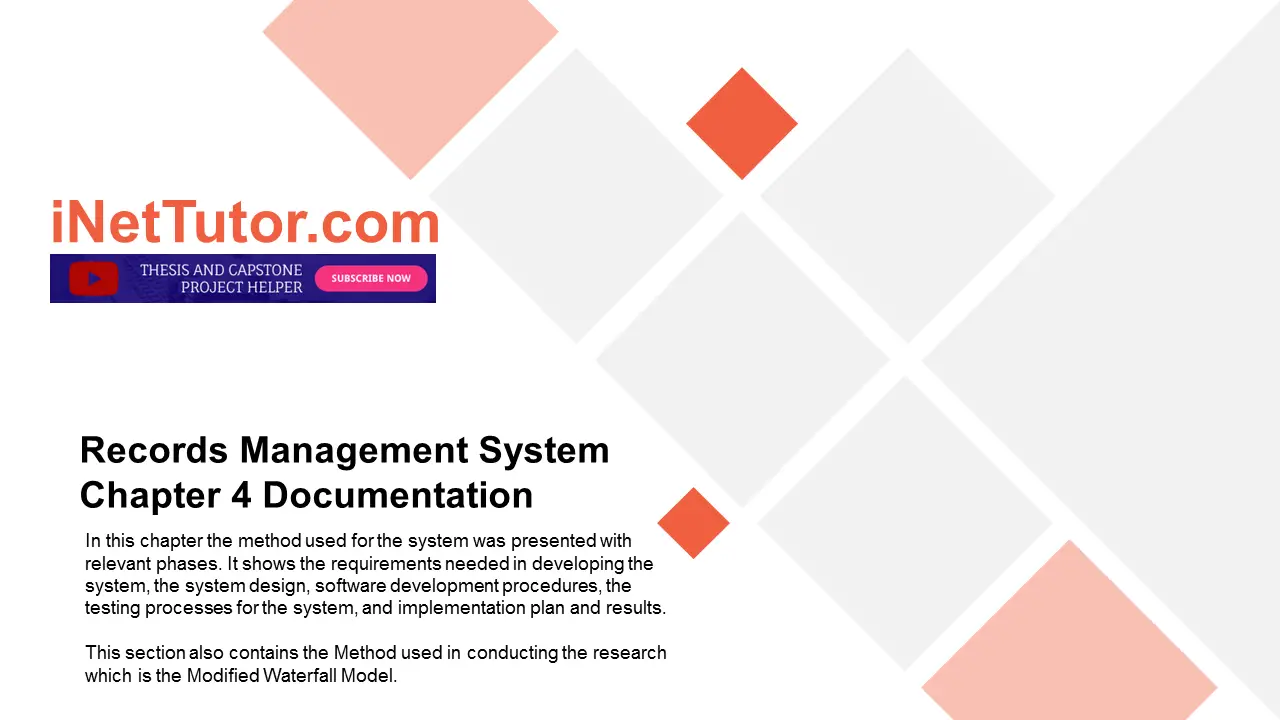
In this chapter the method used for the system was presented with relevant phases. It shows the requirements needed in developing the system, the system design, software development procedures, the testing processes for the system, and implementation plan and results.This section also contains the Method used in conducting the research which is the Modified Waterfall Model.
System Development Life Cycle (SDLC)
The systems development life cycle (SDLC) is a conceptual model used in project management that describes the stages involved in an information system development project, from an initial feasibility study through maintenance of the completed application.
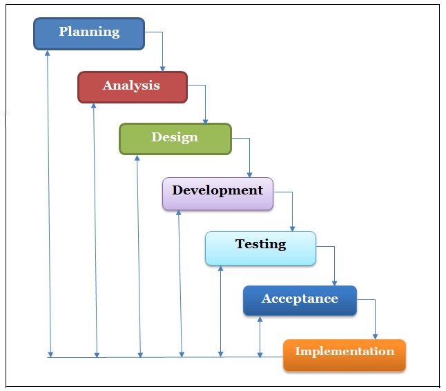
There are various SDLC methodologies have been developed to guide the processes and the researcher used Modified Waterfall Model for the system development. This is the appropriate approach for the Software Development Life Cycle (SDLC) since it involves validation or verification between the phases where any deviations can be corrected immediately, providing the client satisfaction. It includes Planning, Analysis, Design, Development, Testing and Implementation with feedback at every stage.
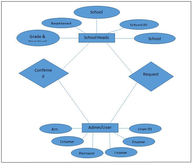
Image may be NSFW. Clik here to view.
Modified Waterfall Model of the Records Management System
Figure 1.0 Shows the Modified Waterfall Model of the Records Management System
Planning
This phase defines the system to be developed, set the project scope and developed the project plan including tasks, resources and timeframe wherein to begin a successful project.
Planning phase is a way in determining solid plan for developing a system. During this phase, the researchers proposed a system to be developed which is feasible to the organization success. It also determined the scope which clearly defines the high level requirements wherein the full functionalities of the system should be accomplished.
Requirements Analysis
In this phase, the development team did gathering of different business requirements to be used in developing the system by where it includes detailed requests of a set of functions and constraints expected by the client in which the researcher must be able to meet to have a successful outcome system. The requirements that are gathered from the client must be analyzed for their validity and the possibility of incorporating them. They then, reviewed, defined and understand the gathered business requirements and documented it.
The development team visits the client and studies their system requirement. They examine the need for possible software automation in the given software system like the required function, behavior, performance and interfacing to understand what type of program to build.
The development team analyzed the project by providing a requirement which is Data Gathering technique to determine the proposed system feasibility within the area to which the study was conducted.
Data Gathering is a technique that contains survey questionnaires about the functionalities of the developed system made by the researcher and to be evaluated to the client.
Survey Questionnaire is a useful tool for gathering information. The questionnaires were conducted to the respondents of the study.
This would be conducted after the validation or verification where any deviation was corrected immediately as one of the research instrument. The researchers provide a number of copies of survey questionnaires to be given to the respondents. In giving the survey questionnaires the researcher was personally administered to the office and after 1 week the researchers collected the questionnaires.
After feasibility study, the development team provides a document that holds the different specific recommendations for the candidate system which consists of personnel assignments and the system functionalities.
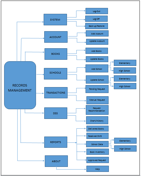
Image may be NSFW. Clik here to view.
Records Management System Chapter 4 Documentation
Requirements Documentation
These are the gathered business requirements from the clients that were reviewed, defined, understand and documented by the researchers:
A system that will lessen the use of paper in recording.
The system must be easy to use and can easily searched records.
The system can easily add, update and print records.
The system will provide secure data and information storage of all the record transactions to help the client operate more efficiently and retrieve records easily when needed.
Software Requirements
The following are the software use for the development and implementation of the system:
Microsoft Visual Studio 2010
Is an integrated development environment (IDE) from Microsoft. It is used to develop console and graphical user interface applications along with Windows Forms or WPF applications, web sites, web applications, web services, and also Windows Store apps in both native codes together with managed code for all platforms. Specifically the researchers used C#.net.
SAP Crystal Reports
Is a business intelligence application, currently marketed to small businesses by SAP AG. It is used to design and generate reports from a wide range of data sources.
Microsoft SQL Server 2008
It is a relational database management system developed by Microsoft. As a database, it is a software product whose primary function is to store and retrieve data as requested by other software applications, be it those on the same computer or those running on another computer across a network (including the Internet).
Peopleware Requirements
The system is design to the need of the records section of the company which provides accurate information and monitoring of the received books, beneficiaries, and other related data.
The system is intended to the person who are managing and monitoring the records of the company.
Initial Testing
During the initial (experts) testing of the system, the researchers used Mc Calls Software Quality Model to evaluate if the system has its function. It can be stated as the process of verifying that the units of code function correctly when integrated.
The Records Management System were rated by the IT Experts using a System Evaluation Criteria given from the researchers. It was rated in terms of the following criteria: AUDIBILITY, ACCURACY, COMMUNICATION COMMONALITY, COMPLETENESS, CONSISTENCY, CONTROLLABILITY, OBSERVABILITY, DATA COMMONALITY, DECOMPOSABILITY, ERROR TOLERANCE, EXECUTION, EFFICIENCY, EXPANDABILITY, GENERALITY, HARDWARE INDEPENDENCE, INSTRUMENT, OPERABILITY, SECURITY, SELF-DOCUMENTATION, SIMPLICITY, SOFTEWARE SYSTEM INDEPENDENCE, TRACEABILITY, and TRAINING.
The rating scale were used to measured used by the researcher was the scale from 1-5, where 5(very good), 4(good), 3(average), 2(fair) and 1(poor). And it would be rated by 3 IT Experts.
Final Testing
During the final (user acceptance) testing of the system, the researchers used the user acceptance questionnaire to evaluate if the system satisfies the business requirements. It can be stated as the process of validating and verifying that a system meets the requirements that guided its design and development, works as expected, and satisfies the needs of client.
The system were evaluated by the end-users using a User Acceptance Testing Questionnaires given by the researchers. It was rated in terms of the following criteria: INFORMATION IN THE PROGRAM, USER INTERACTION and TECHNICAL ASPECTS OF THE SOFTWARE AND MATERIALS.
The rating measured used by the researcher was the scale from 1-5, where 5(Excellent), 4(Very Good), 3(Good),2(Fair) and 1(Poor).
Credits to the researchers and developers of the project
You may visit our facebook page for more information, inquiries and comments.
Computerizations and system development have made possible solutions for the operations of the computer easy enough in processing record systems such as, creation of data records, storing, filing and retrieval of data. The [state the name of the school/college/academic institution] had increased in student`s population and at the same time, the number of works of the registrar and student`s grades to be processed has also increased. The registrar office encoded the grades of the students once the instructors submitted their report card. The registrar office will release the grades of the students after they encode and the students can get their grades from the registrar office. One of the responsibilities of the registrar office is to keep the student`s grades data secured for their records and purposes. As the number of students increases, using a manual process in grade distribution is not reliable. It will take an hour or days to release grades to every student for record or enrollment purposes. These process of grades inquiry was inconvenient, tiresome and at common instance time consuming and costly. The students need to go directly to their respective instructor in order to inquire and get their grades for later purposes. To ease these difficulties in getting and viewing their grades, a student can now login using his/her logon credentials on the website. Since internet service seems to be a positive feature which most individual`s engage, and access almost in all places via an internet capable mobile phones or a regular computer, it is therefore an extremely effective means of transporting grade information to them quicker and easier.
Image may be NSFW. Clik here to view.
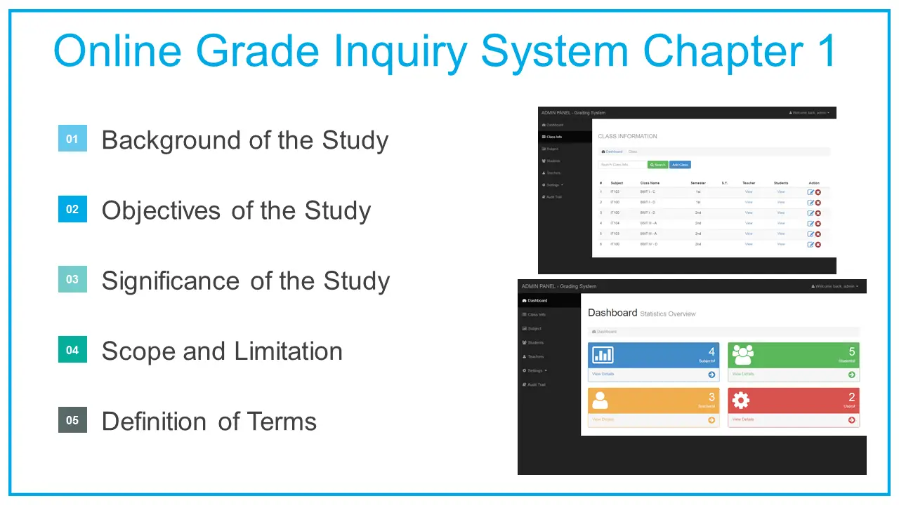
Online Grade Inquiry System Chapter 1
Hence, the researcher came with an idea of developing an Online Grade inquiry system which is based on a website. This will eventually help in providing an efficient and accurate grade reports to the students with a minimal effort to exert in knowing their grade details every end of the semester. Moreover, student’s grades were encoded directly in the online grade inquiry system database. Students will able to view their grades anywhere and anytime provided that they have an internet connection by using an internet capable phone or a computer. Upon viewing, they will be able to print for themselves a computer generated summary of their grades for the said semester.
OBJECTIVES OF THE STUDY
Generally, this study generally aims to develop an ONLINE GRADE INQUIRY SYSTEM for [state the name of the school/college/academic institution].
Specifically the study aims to;
Develop an online grade inquiry system using html5, php and mysql.
Provide grade details of every student on a specified semester and school year.
Enable instructors encode their student’s grades online.
Evaluate the developed system in terms of its accessibility, navigation, design, content and security.
SIGNIFICANCE OF THE STUDY
This study was made to find out that the use of online grade inquiry system will enhance the process on the releasing of grades to the students. This study will benefit the following key personnel’s:
Teachers of [state the name of the school/college/academic institution] it can help them encode the grades of students for each subject area through online grading system.
Students of [state the name of the school/college/academic institution] it can help them to inquire their grades in a more efficient way. They can get their summary of grades through the website and be able to print it on a paper form report.
Registrar of [state the name of the school/college/academic institution] it can help them to lessen their tasks in preparing of summary of grades of the students.
SCOPE AND LIMITATION
Scope The request of the grades can be done through any network of internet connection using a regular computer or mobile phones. The website supports aut0-responsive mechanics which means the site could be opened using an internet capable phone. The registrar can set activity announcement, course, day, rooms, school year , semester ,subjects , time and unit The registrar can also add grades, load subjects, add students and add instructor details. The registrar can add teacher details. The instructors can encode grades of the students on the database of the hosted online grade inquiry system. Only the registered students are qualified to inquire their grades. The students can inquire grades via the website by entering their login credentials. Limitation it cannot be used for conversation. If the instructor submitted wrong grades of student, the online system is not reliable in human error. The grade encoding process relies on Internet connection. The system was only hosted using a free domain service and is not running an actual domain service.
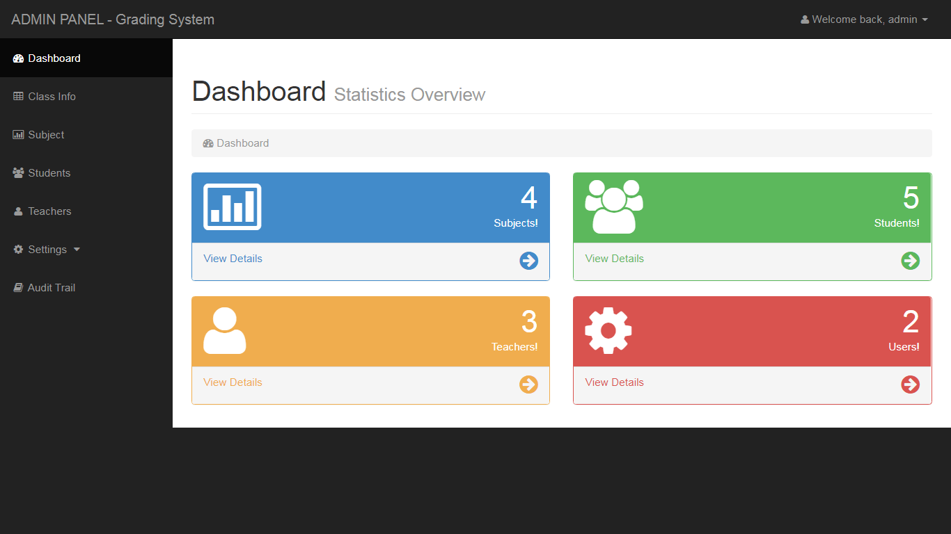
Image may be NSFW. Clik here to view.
Online Grade Inquiry System Dashboard
OPERATIONAL DEFINITION OF TERMS
DATABASE is systematically organized or structured repository of indexed information (usually as a group of linked data files) that allows easy retrieval, updating, analysis, and output of data.
ENCODE to convert (a message) from plain text into code.
GRADES an accepted level or standard of institution.
INQUIRY a seeking for information by asking questions.
ONLINE computer or device connected to a network (such as Internet) and ready to use (or be used by) other computers or devices.
PHP a server side type of programming which suitable for the creation of web pages. · WEB a complex system of interconnected elements.
CSS is a style sheet language used for describing the look and formatting of a document written in a markup language.
HTML5 is a core technology markup language of the Internet used for structuring and presenting content for the World Wide Web. · DREAMWEAVER -front end software used in designing the system and coding. PHPMYADMIN – a free software tool written in PHP, intended to handle the administration of MySQL over the Web.
WAMPP -windows web development environment it allows you to create web applications with Apache2, Php and a MySQL database.
Image may be NSFW. Clik here to view.
Online Grade Inquiry System
Credits to the researchers and developers of the project
You may visit our facebook page for more information, inquiries and comments.
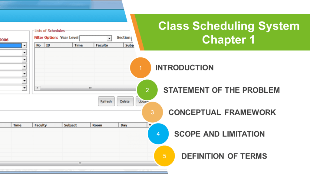
The project entitled class scheduling system is a solution that will replace the manual method of preparing a schedule of classes. This article is an example of chapter 1 documentation of the said project; this is based on a thesis format provided by a certain school/college. Our team can provide you with the revised format based on your requirements/outline.
This chapter discusses the statement of the problem, hypothesis, theoretical/conceptual framework, significance of the study, scope and limitation of the study and definition of terms.
INTRODUCTION
One of the many things schools and universities have in common is the need for scheduling. People scheduling, class scheduling, events scheduling, etc. However, inefficient scheduling can lead to conflicts or double bookings, inefficient use of rooms and resources, and more (http://www.peoplecube.com).
Class schedules are planned for smooth operation purposes and are subject to change in case to case basis. Although we make every reasonable effort to avoid making changes on posted schedules, it is sometimes necessary to add or delete courses, change times, days, or locations of courses, change academic calendar dates or cancel courses for insufficient registration and/or academic/administrative decision (http://www.law.seattleu.edu).
Class scheduling refers to the process of preparing a class schedule. Class schedule shows subject, time allotment, days, room utilization, instructor, and class adviser. Both instructor and student use it for reference as classes begin. The [name of the school] uses this for classroom monitoring and classroom observation.
The class scheduling of [name of the school] is designed while considering the instructors’ and students’ availability. Since most instructors are part-time employees, class schedule system permits employees to work according to their available time.
Students’ safety and concerns are also considered in preparing the class schedule. The department chairman is using Microsoft Excel or manual procedures in preparing schedule of classes.
It was found out that the start of classes every semester is delayed due to late posting of class schedule because of conflicts in time, subjects and room assignment. This problem is always encountered by the department chairman, students and instructors.
This study is conducted in order to identify possible solutions to the problems met by the instructors, class advisers, students, department chair, and of the school as a whole.
STATEMENT OF THE PROBLEM
This study aims to assess the class scheduling system of [name of the school].
Specifically, the study sought to answer the following questions:
What are the procedures employed by the [name of the school] in class scheduling?
What are the problems encountered by the students and instructors with regards to class schedule as to:
speed
accuracy
efficiency
What is the level of acceptability of the current scheduling system to the students, faculty and department chairman?
What is the level of need for developing Automated Class Scheduler as perceived by the students, faculty and department chairman?
ASSUMPTIONS OF THE STUDY
The following were the assumptions formulated by the researchers based on the problems stated:
The level of acceptability of the present scheduling system among students, faculty and department chairman is low.
The level of need for developing the Automated Class Scheduler as perceived by students, faculty and the department chairperson is high.
THEORETICAL FRAMEWORK OF THE STUDY
Class Scheduling System will be created specifically for the [name of the school] to provide accuracy, speed and effective class schedule.
Class Scheduler is easy to use whether in single or multi-user application that helps students and school administrators quickly schedule students’ classes. The software is ideal both for high school and college. The idea behind Class Scheduler is to increase the productivity of classroom administrators by automating the class scheduling process. Class Scheduler also has visual scheduling features. Classes can be deleted, added and assigned to different rooms by the instructor right from the schedule view. Class times can even be moved around using drag and drop, adjusting or by resizing individual classes (http://www.CyberMatrix.com).
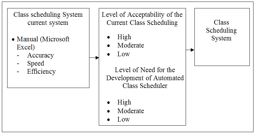
CONCEPTUAL FRAMEWORK OF THE STUDY
This study aims to assess the class scheduling system of [name of the school] in terms of speed, accuracy and efficiency. When the performance of the current system is low in terms of speed, accuracy and efficiency, the class scheduler system is highly recommended.
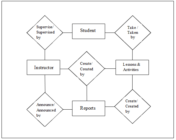
Image may be NSFW. Clik here to view.
Schematic Diagram of Class Scheduling System
Schematic Diagram Illustrating the Conceptual Framework of the Study
SIGNIFICANCE OF THE STUDY
The persons who will benefit by this study are the following:
Department Chairman. The proposed system will benefit the department chairman in creating a flexible scheduling option that will let her/him build virtually any type of schedule.
Instructors. Instructors can start classes on time without experiencing conflicts as to schedule and room assignments.
Students. The proposed system will help students determine their class schedule before the start of the semester.
Researchers. This study will provide other researchers’ cases to study other variables not
covered in this study.
Future Researchers. The time allotted for the development of the system is limited, that’s why it will be an opportunity for the next batch of researchers to review the project and apply the necessary changes and updates.
SCOPE AND LIMITATION OF THE STUDY
This study was conducted at [name of the school] and focused on the development of Class Scheduling System. This includes subjects, time, day’s allotment, room utilization, instructors and class advisers.
The findings of this study were based on the answers of the respondents in the instrument used. The interpretation of the results is limited only to the statistical tools in the study.
DEFINITION OF TERMS
In order to provide clear interpretation of basic concept used in this study, the following terms are conceptually and operationally defined.
Accuracy – The degree of closeness of a measured and calculated quantity to its actual (true value) (http://en.wikipedia.org). Operationally, this is used to measure the correctness in preparing class schedule.
School – Provides quality general education to enable students to think critically, communicate effectively, complete accurately and adapt to change appropriately (www.umcc/genral_edu.ph). Operationally, in this study, it is the cooperating agency where the study was conducted.
Class Scheduler – known as college style scheduling, is a form of hand scheduling that uses information from the Master Schedule and produces cards or labels with the course information printed on them (http://www.CyberMatrix.com). Operationally, as used in this study, it is the Automated Class scheduler proposed by the researchers.
Department Chairman – acts or presides as chair, as of an academic department in a university (www.answers.com). Operationally, the department chair is a faculty member responsible for the daily operation of the program as well as long-term oversight of planning, scheduling, and curriculum development.
Efficiency – In mechanics, the measure of the effectiveness with which a system performs (www.answers.com). Operationally, it is used to measure the effectiveness of class schedule.
Instructors –The entire teaching staff of a university, college, or school, including any administrators holding academic rank (http://encyclopedia.thefreedictionary.com). Operationally, it refers to the faculty of [name of the school] who were one of the respondents of the study.
Level of Need – needs might include demand for a particular type of business, for a certain government program or entity, or for individuals with particular skills (http://en.wikipedia.org). Operationally, it necessitates the development of an Automated Class Scheduler to improve the academic class schedule.
Level of Acceptability – The quality of being acceptable (http://www.thinkexit.com). Operationally, the assessment used to determine the acceptability level of the class schedule of students and faculty prepared by the [name of the school].
Speed – The rate at which something moves or travels (http://pimsleur.english-test.net). Operationally, it refers to how fast the preparation of the class schedule of the [name of the school] is done.
Credits to the researchers and developers of the project
You may visit our facebook page for more information, inquiries and comments.
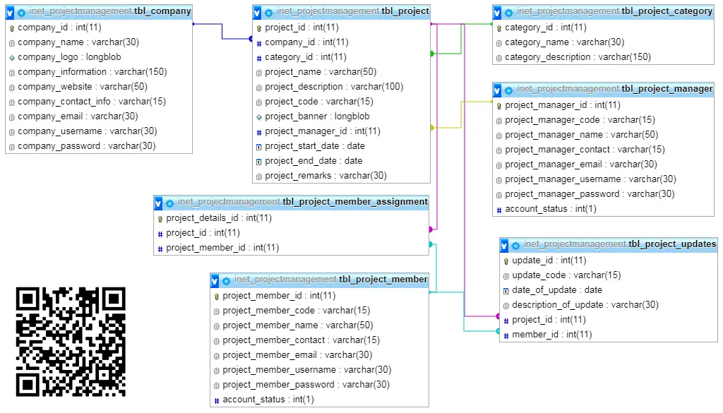
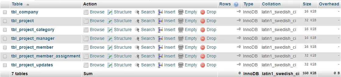
This article will provide you with the list of tables and entities for every table in the development of project management system.
This is the first phase of the project, next is to prepare the screen design and layout of the system and it will be converted into html file using the Bootstrap Framework. Functions of the system will be the last part of the development; the developers will use PHP as the scripting language.
tbl_project – information of the project will recorded and stored in the tbl_project table, the table has 10 attributes as presented below.
project_id – this is the primary key of the table.
company_id – this is a foreign key that links to the information of company in the tbl_company. it refers to the company that owns and requested the project.
category_id – category of the project.
project_name – refers to the name of the project.
project_description – detailed information about the project.
project_code – the reference code that will be used in the monitoring of project.
project_banner – the image that will be uploaded to represent the project.
project_manager_id – the foreign key that links to the project manager in the tbl_project_manager table. It refers to the project manager who will manage the project.
project_start_date – the date the project will start.
project_end_date – the date the project will end.
project_remarks – the status of the project, comments, notes and observations about the project.
Create SQL Statement – the statement below is used to create the tbl_project, copy the sql statement and paste it in the sql manager/tab of your phpmyadmin.
CREATE TABLE IF NOT EXISTS `tbl_project` (
`project_id` int(11) NOT NULL AUTO_INCREMENT,
`company_id` int(11) NOT NULL,
`category_id` int(11) NOT NULL,
`project_name` varchar(50) NOT NULL,
`project_description` varchar(100) NOT NULL,
`project_code` varchar(15) NOT NULL,
`project_banner` longblob NOT NULL,
`project_manager_id` int(11) NOT NULL,
`project_start_date` date NOT NULL,
`project_end_date` date NOT NULL,
`project_remarks` varchar(30) NOT NULL,
PRIMARY KEY (`project_id`),
KEY `company_id` (`company_id`,`project_manager_id`),
KEY `category_id` (`category_id`),
KEY `project_manager_id` (`project_manager_id`)
) ENGINE=InnoDB DEFAULT CHARSET=latin1 AUTO_INCREMENT=1 ;
tbl_project_member_assignment – this table is used to store the list of project members that will be a part of the project development and maintenance.
project_details_id – this is the primary key of the table, it is usually unique and duplicate entry is not allowed.
project_id – the foreign key that links to the tbl_project table.
project_member_id – it refers to the project members that will be a part of the project, it is a foreign key that links to the tbl_project_members.
Create SQL Statement – the statement below is used to create the tbl_project_member_assignment, copy the sql statement and paste it in the sql manager/tab of your phpmyadmin.
CREATE TABLE IF NOT EXISTS `tbl_project_member_assignment` (
`project_details_id` int(11) NOT NULL AUTO_INCREMENT,
`project_id` int(11) NOT NULL,
`project_member_id` int(11) NOT NULL,
PRIMARY KEY (`project_details_id`),
KEY `project_id` (`project_id`,`project_member_id`),
KEY `project_member_id` (`project_member_id`)
) ENGINE=InnoDB DEFAULT CHARSET=latin1 AUTO_INCREMENT=1 ;
tbl_project_manager – information of the project manager will be stored in this table and it has 8 attributes.
project_manager_id – primary key of the table.
project_manager_code – the code given by the system to the project managers, this serves as their reference number.
project_manager_name – the fullname of the project manager.
project_manager_contact – contact number information of the project manager.
project_manager_email – email address of the project manager.
project_manager_username – the desired username of the project manager, this can be manage by the project manager.
project_manager_password – the desired password of the project manager, this can be manage by the project manager. For security purpose the minimum password length is set to 12 characters.
account_status – this is for the activation and deactivation of the user account. Deactivated account can no longer access the platform.
Create SQL Statement – the statement below is used to create the tbl_project_manager, copy the sql statement and paste it in the sql manager/tab of your phpmyadmin.
CREATE TABLE IF NOT EXISTS `tbl_project_manager` (
`project_manager_id` int(11) NOT NULL AUTO_INCREMENT,
`project_manager_code` varchar(15) NOT NULL,
`project_manager_name` varchar(50) NOT NULL,
`project_manager_contact` varchar(15) NOT NULL,
`project_manager_email` varchar(30) NOT NULL,
`project_manager_username` varchar(30) NOT NULL,
`project_manager_password` varchar(30) NOT NULL,
`account_status` int(1) NOT NULL,
PRIMARY KEY (`project_manager_id`)
) ENGINE=InnoDB DEFAULT CHARSET=latin1 AUTO_INCREMENT=1 ;
tbl_project_category – the project were group according to the scope and nature of the project, this is the table that list down those groups.
category_id – primary key of the table.
category_name – name of category.
category_description – description of the category.
Create SQL Statement – the statement below is used to create the tbl_project_category, copy the sql statement and paste it in the sql manager/tab of your phpmyadmin.
CREATE TABLE IF NOT EXISTS `tbl_project_category` (
`category_id` int(11) NOT NULL AUTO_INCREMENT,
`category_name` varchar(30) NOT NULL,
`category_description` varchar(150) NOT NULL,
PRIMARY KEY (`category_id`)
) ENGINE=InnoDB DEFAULT CHARSET=latin1 AUTO_INCREMENT=1 ;
tbl_company – company information will be stored in the tbl_company table. The table has 10 fields or column.
company_id – primary key of the table.
company_name – the name of the company.
company_logo – logo or banner of the company.
company_information – information about the company such as the about us, vmgo, etc.
company_website – the website of the company (if applicable).
company_contact_info – contact information of the company.
company_email – email address of the company.
company_username – username of the representative delegated by the company in this platform.
company_password – password used to access the platform.
company_account_status – this is for the activation and deactivation of the user account. Deactivated account can no longer access the platform.
Create SQL Statement – the statement below is used to create the tbl_company, copy the sql statement and paste it in the sql manager/tab of your phpmyadmin.
CREATE TABLE IF NOT EXISTS `tbl_company` (
`company_id` int(11) NOT NULL AUTO_INCREMENT,
`company_name` varchar(30) NOT NULL,
`company_logo` longblob NOT NULL,
`company_information` varchar(150) NOT NULL,
`company_website` varchar(50) NOT NULL,
`company_contact_info` varchar(15) NOT NULL,
`company_email` varchar(30) NOT NULL,
`company_username` varchar(30) NOT NULL,
`company_password` varchar(30) NOT NULL,
PRIMARY KEY (`company_id`)
) ENGINE=InnoDB DEFAULT CHARSET=latin1 AUTO_INCREMENT=1 ;
tbl_project_member – this table will store the information of the project members that will be a part of the project development.
project_member_id – primary key of the table.
project_ member _code – the code given by the system to the project member, this serves as their reference number.
project_ member _name – the fullname of the project member.
project_ member _contact – contact number information of the project member.
project_ member _email – email address of the project member.
project_ member _username – the desired username of the project member, this can be manage by the project member.
project_ member _password – the desired password of the project member, this can be manage by the project member. For security purpose the minimum password length is set to 12 characters.
account_status – this is for the activation and deactivation of the user account. Deactivated account can no longer access the platform.
Create SQL Statement – the statement below is used to create the tbl_project_member, copy the sql statement and paste it in the sql manager/tab of your phpmyadmin.
CREATE TABLE IF NOT EXISTS `tbl_project_member` (
`project_member_id` int(11) NOT NULL AUTO_INCREMENT,
`project_member_code` varchar(15) NOT NULL,
`project_member_name` varchar(50) NOT NULL,
`project_member_contact` varchar(15) NOT NULL,
`project_member_email` varchar(30) NOT NULL,
`project_member_username` varchar(30) NOT NULL,
`project_member_password` varchar(30) NOT NULL,
`account_status` int(1) NOT NULL,
PRIMARY KEY (`project_member_id`)
) ENGINE=InnoDB DEFAULT CHARSET=latin1 AUTO_INCREMENT=1 ;
tbl_project_updates – the list of updates for every project will be stored in this table, it has 6 attributes as presented below.
update_id – primary key of the table.
update_code – code reference of the update transaction.
date_of_update – the date the update was created.
description_of_update – remarks, comments and description of the update
project_id – the foreign key that links to the project information (tbl_project).
member_id – the project member who posted the update. Foreign key that links to the tbl_project_member table
Create SQL Statement– the statement below is used to create the tbl_project_updates, copy the sql statement and paste it in the sql manager/tab of your phpmyadmin.
CREATE TABLE IF NOT EXISTS `tbl_project_updates` (
`update_id` int(11) NOT NULL AUTO_INCREMENT,
`update_code` varchar(15) NOT NULL,
`date_of_update` date NOT NULL,
`description_of_update` varchar(30) NOT NULL,
`project_id` int(11) NOT NULL,
`member_id` int(11) NOT NULL,
PRIMARY KEY (`update_id`),
KEY `project_id` (`project_id`,`member_id`),
KEY `member_id` (`member_id`)
) ENGINE=InnoDB DEFAULT CHARSET=latin1 AUTO_INCREMENT=1 ;
Image may be NSFW. Clik here to view.
Project Management System List of Database Tables
Constraints for dumped tables
—
— Constraints for table `tbl_project`
—
ALTER TABLE `tbl_project`
ADD CONSTRAINT `tbl_project_ibfk_3` FOREIGN KEY (`project_manager_id`) REFERENCES `tbl_project_manager` (`project_manager_id`) ON DELETE CASCADE ON UPDATE CASCADE,
ADD CONSTRAINT `tbl_project_ibfk_1` FOREIGN KEY (`category_id`) REFERENCES `tbl_project_category` (`category_id`) ON DELETE CASCADE ON UPDATE CASCADE,
ADD CONSTRAINT `tbl_project_ibfk_2` FOREIGN KEY (`company_id`) REFERENCES `tbl_company` (`company_id`) ON DELETE CASCADE ON UPDATE CASCADE;
—
— Constraints for table `tbl_project_member_assignment`
—
ALTER TABLE `tbl_project_member_assignment`
ADD CONSTRAINT `tbl_project_member_assignment_ibfk_2` FOREIGN KEY (`project_member_id`) REFERENCES `tbl_project_member` (`project_member_id`) ON DELETE CASCADE ON UPDATE CASCADE,
ADD CONSTRAINT `tbl_project_member_assignment_ibfk_1` FOREIGN KEY (`project_id`) REFERENCES `tbl_project` (`project_id`) ON DELETE CASCADE ON UPDATE CASCADE;
—
— Constraints for table `tbl_project_updates`
—
ALTER TABLE `tbl_project_updates`
ADD CONSTRAINT `tbl_project_updates_ibfk_2` FOREIGN KEY (`member_id`) REFERENCES `tbl_project_member` (`project_member_id`) ON DELETE CASCADE ON UPDATE CASCADE,
ADD CONSTRAINT `tbl_project_updates_ibfk_1` FOREIGN KEY (`project_id`) REFERENCES `tbl_project` (`project_id`) ON DELETE CASCADE ON UPDATE CASCADE;
You may visit our facebook page for more information, inquiries and comments.
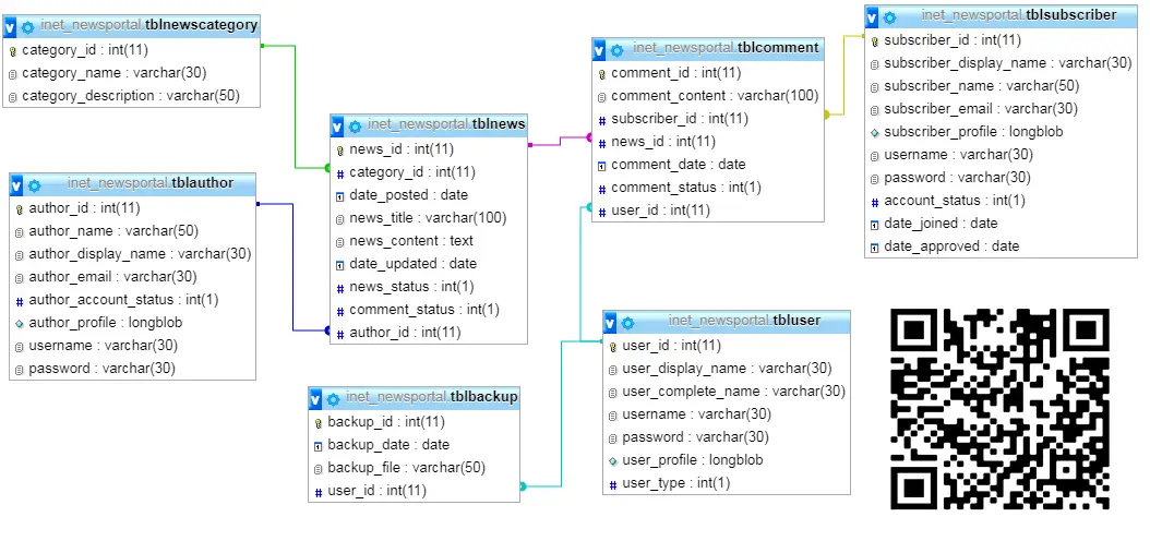
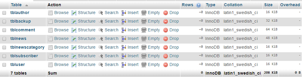
This article will provide you with the list of tables and entities for every table in the development of news portal system. The team will later provide a video tutorial on how to create the database in PHPMyAdmin.
Image may be NSFW. Clik here to view.
News Portal Database Design Table Relationship
tblnews – this is the main table of the system, this is where the news will be stored. The tblnews has 9 fields.
news_id – this is the primary key of the table.
category_id – the news will be grouped according to their type and its content; this is the foreign key that links to the tblnewscategory table.
date_posted – this column refers to the posting date of the news or article.
news_title – the title of the content or news.
news_content – the body of the news.
date_updated – this will record the date when the author updates the contents of the news.
news_status – this column has two values 0 and 1, 0 for unpublished, 1 for published.
comment_status – the author can set the news if it can accept comment or not.
author_id – this column represents the author of the article. This is a foreign key that links to the tblauthor.
Create SQL Statement – the statement below is used to create the tblnews, copy the sql statement and paste it in the sql manager/tab of your phpmyadmin.
CREATE TABLE IF NOT EXISTS `tblnews` (
`news_id` int(11) NOT NULL AUTO_INCREMENT,
`category_id` int(11) NOT NULL,
`date_posted` date NOT NULL,
`news_title` varchar(100) NOT NULL,
`news_content` text NOT NULL,
`date_updated` date NOT NULL,
`news_status` int(1) NOT NULL,
`comment_status` int(1) NOT NULL,
`author_id` int(11) NOT NULL,
PRIMARY KEY (`news_id`),
KEY `category_id` (`category_id`,`author_id`),
KEY `author_id` (`author_id`)
) ENGINE=InnoDB DEFAULT CHARSET=latin1 AUTO_INCREMENT=1 ;
tblnewscategory – this table will store the list of news category of the system. it has 3 columns as presented below.
category_id – primary key of the table.
category_name – name of the category.
category_description – brief description about the category.
Create SQL Statement – the statement below is used to create the tblnewscategory, copy the sql statement and paste it in the sql manager/tab of your phpmyadmin.
CREATE TABLE IF NOT EXISTS `tblnewscategory` (
`category_id` int(11) NOT NULL AUTO_INCREMENT,
`category_name` varchar(30) NOT NULL,
`category_description` varchar(50) NOT NULL,
PRIMARY KEY (`category_id`)
) ENGINE=InnoDB DEFAULT CHARSET=latin1 AUTO_INCREMENT=1 ;
tblauthor – authors are the one who can create and post an article to the system. This is the table that stores the information about the authors. It has 8 columns.
author_id – primary key of the table.
author_name – complete name of the author.
author_display_name – the name that will be displayed in the article. This column serves as the code name of the author.
author_email – email address of the author.
author_account_status – account status refers to the login status of the author, 0 is for deactivated, and 1 is for activated.
author_profile – the profile image of the author.
username – the desired username of the author.
password – the desired password of the author, at least minimum of 8 characters.
Create SQL Statement – the statement below is used to create the tblauthor, copy the sql statement and paste it in the sql manager/tab of your phpmyadmin.
CREATE TABLE IF NOT EXISTS `tblauthor` (
`author_id` int(11) NOT NULL AUTO_INCREMENT,
`author_name` varchar(50) NOT NULL,
`author_display_name` varchar(30) NOT NULL,
`author_email` varchar(30) NOT NULL,
`author_account_status` int(1) NOT NULL,
`author_profile` longblob NOT NULL,
`username` varchar(30) NOT NULL,
`password` varchar(30) NOT NULL,
PRIMARY KEY (`author_id`)
) ENGINE=InnoDB DEFAULT CHARSET=latin1 AUTO_INCREMENT=1 ;
tblsubscriber – subscriber refers to the users/visitors that is registered in the website.
subscriber_id – primary key of the table.
subscriber_display_name – the code name of the subscriber, they can choose to display their real name or their code name.
subscriber_name – this field will store the real name of the subscriber.
subscriber_email – email address of the subscriber, they can receive updates from the site through their email address.
subscriber_profile – the image profile of the subscriber.
username – the desired username of the subscriber.
password – the desired password of the subscriber, at least minimum of 8 characters.
account_status – account status refers to the login status of the subscriber, 0 is for deactivated, and 1 is for activated.
date_joined – the registration date of the subscriber.
date_approved – the account will be reviewed by the administrator and this column refers to the approval date.
Create SQL Statement – the statement below is used to create the tblsubscriber, copy the sql statement and paste it in the sql manager/tab of your phpmyadmin.
CREATE TABLE IF NOT EXISTS `tblsubscriber` (
`subscriber_id` int(11) NOT NULL AUTO_INCREMENT,
`subscriber_display_name` varchar(30) NOT NULL,
`subscriber_name` varchar(50) NOT NULL,
`subscriber_email` varchar(30) NOT NULL,
`subscriber_profile` longblob NOT NULL,
`username` varchar(30) NOT NULL,
`password` varchar(30) NOT NULL,
`account_status` int(1) NOT NULL,
`date_joined` date NOT NULL,
`date_approved` date NOT NULL,
PRIMARY KEY (`subscriber_id`)
) ENGINE=InnoDB DEFAULT CHARSET=latin1 AUTO_INCREMENT=1 ;
tblcomment – this is the table that stores the comments of the subscribers to the news/article/post. The table has 7 columns.
comment_id – primary key of the table.
comment_content – the comment of the subscriber will be stored in this column.
subscriber_id – this is a foreign key that links to the tblsubscriber, this column refers to the subscriber who posted a comment into the article.
news_id – this is a foreign key that links to the tblnews table.
comment_date – the posting date of the comment.
comment_status – comments will not be automatically posted on the website, it will be reviewed first by the administrator/moderator of the system.
user_id – the user who approves the comment.
Create SQL Statement – the statement below is used to create the tblcomment, copy the sql statement and paste it in the sql manager/tab of your phpmyadmin.
CREATE TABLE IF NOT EXISTS `tblcomment` (
`comment_id` int(11) NOT NULL AUTO_INCREMENT,
`comment_content` varchar(100) NOT NULL,
`subscriber_id` int(11) NOT NULL,
`news_id` int(11) NOT NULL,
`comment_date` date NOT NULL,
`comment_status` int(1) NOT NULL,
`user_id` int(11) NOT NULL,
PRIMARY KEY (`comment_id`),
KEY `subscriber_id` (`subscriber_id`,`user_id`),
KEY `news_id` (`news_id`),
KEY `user_id` (`user_id`)
) ENGINE=InnoDB DEFAULT CHARSET=latin1 AUTO_INCREMENT=1 ;
tbluser – this will store the administrator and moderator information of the system.
user_id – primary key of the table.
user_display_name – the code name of the user.
user_complete_name – the real name of the user.
username – username assigned to the user.
password – the desired password of the user, at least minimum of 8 characters.
user_profile – image profile of the user.
user_type – user category of the user; 0 for administrator and 1 for moderator.
Create SQL Statement – the statement below is used to create the tbluser, copy the sql statement and paste it in the sql manager/tab of your phpmyadmin.
CREATE TABLE IF NOT EXISTS `tbluser` (
`user_id` int(11) NOT NULL AUTO_INCREMENT,
`user_display_name` varchar(30) NOT NULL,
`user_complete_name` varchar(30) NOT NULL,
`username` varchar(30) NOT NULL,
`password` varchar(30) NOT NULL,
`user_profile` longblob NOT NULL,
`user_type` int(1) NOT NULL,
PRIMARY KEY (`user_id`)
) ENGINE=InnoDB DEFAULT CHARSET=latin1 AUTO_INCREMENT=1 ;
tblbackup
backup_id
backup_date
backup_file
user_id
Create SQL Statement – the statement below is used to create the tblbackup, copy the sql statement and paste it in the sql manager/tab of your phpmyadmin.
CREATE TABLE IF NOT EXISTS `tblbackup` (
`backup_id` int(11) NOT NULL AUTO_INCREMENT,
`backup_date` date NOT NULL,
`backup_file` varchar(50) NOT NULL,
`user_id` int(11) NOT NULL,
PRIMARY KEY (`backup_id`),
KEY `user_id` (`user_id`)
) ENGINE=InnoDB DEFAULT CHARSET=latin1 AUTO_INCREMENT=1 ;
Image may be NSFW. Clik here to view.
News Portal Database Design List of Tables
Constraints for dumped tables
—
— Constraints for table `tblbackup`
—
ALTER TABLE `tblbackup`
ADD CONSTRAINT `tblbackup_ibfk_1` FOREIGN KEY (`user_id`) REFERENCES `tbluser` (`user_id`) ON DELETE CASCADE ON UPDATE CASCADE;
—
— Constraints for table `tblcomment`
—
ALTER TABLE `tblcomment`
ADD CONSTRAINT `tblcomment_ibfk_3` FOREIGN KEY (`user_id`) REFERENCES `tbluser` (`user_id`) ON DELETE CASCADE ON UPDATE CASCADE,
ADD CONSTRAINT `tblcomment_ibfk_1` FOREIGN KEY (`subscriber_id`) REFERENCES `tblsubscriber` (`subscriber_id`) ON DELETE CASCADE ON UPDATE CASCADE,
ADD CONSTRAINT `tblcomment_ibfk_2` FOREIGN KEY (`news_id`) REFERENCES `tblnews` (`news_id`) ON DELETE CASCADE ON UPDATE CASCADE;
—
— Constraints for table `tblnews`
—
ALTER TABLE `tblnews`
ADD CONSTRAINT `tblnews_ibfk_2` FOREIGN KEY (`author_id`) REFERENCES `tblauthor` (`author_id`) ON DELETE CASCADE ON UPDATE CASCADE,
ADD CONSTRAINT `tblnews_ibfk_1` FOREIGN KEY (`category_id`) REFERENCES `tblnewscategory` (`category_id`) ON DELETE CASCADE ON UPDATE CASCADE;
You may visit our facebook page for more information, inquiries and comments.
Web Based Elearning about Computer Hardware Chapter 4
This article includes the different diagrams such as the decomposition diagram, data flow diagram and er diagram of the web based elearning system. It also includes the software development tools used and as well as the testing plan.
Requirements Analysis and Documentation
The researchers make the necessary preparation to develop a CAI Web Based Elearning about Computer Hardware. In order for the researchers to develop CAI Web Based Elearning about Computer Hardware, the researchers used different procedures to attain that objective. Included here are the casual interviews where the researchers ask some questions to the IT instructor about the traditional way of teaching and what would be the effect of it to the students. Query was made if this kind of teaching is effective in motivating the students. We establish basis to learn its disadvantages and advantages, and what are the suggestions and recommendations of the instructor due to this type of teaching. The researcher was directed by the objectives of the study and by the framework that serves as basis of the step by step process in acquiring result of the investigation. Through the review of related literature, the researcher has gleaned overview of what has been studied by key writers and previous researchers that give insight regarding the prevailing theories, and hypothesis and methodologies.
Through the use of online articles like blogs and early research of the topic; the researchers were able to understand more of the need to carry out the study and the impact of this in addressing current problems pertinent to this area.
Next is the preparation of the study materials. The materials being prepared are Documents, Presentation, Modules, Movie Clips, and downloaded materials from the internet which is related to the study.
Lastly, and the most important material of this study are the requirements of the software which will be used in running the Web Based Elearning about Computer Hardware. The researchers’ study is web-based. So, the researchers used Moodle in developing the Web Based Elearning about Computer Hardware.
Design of Software with Processes
The researchers created a design based on the result of the requirements procedure to be developed. Figure 2.0 shows the Decomposition of Web Based Elearning about Computer Hardware.
Image may be NSFW. Clik here to view.Decomposition Chart of Web Based Elearning about Computer Hardware
Figure 2.0 Decomposition of Web Based Elearning about Computer Hardware
The CAI Web Based Elearning about Computer Hardware has an Admin Page which can administer all the blocks and editing of your Moodle site, while the Student’s Page or Teacher’s Page are the page for the users. Logout allows you to exit the Moodle site. The Navigation block provides easy access to view various sections of the Moodle site and includes My Home a personalized home page displaying links to the courses a user is associated with and activity information. Site Pages which links to site pages and resources from the front page of Moodle. My Profile allows a user to view their profile, forums posts, blogs and messages as well as manage their private files. My Courses are lists and links to courses the user is associated with. The Settings block provides you with easy access to change various settings of a Moodle site. All users have access to edit their profile and message settings from this block as well as their Blog preferences. My Profile Settings allows you to access the editing, changing password, roles, messaging and blogs that are included to your Moodle profile.
Figure 3.0 shows the Data Flow Diagram Context Diagram of the developed Web Based Elearning about Computer Hardware.
Image may be NSFW. Clik here to view.DFD Context Diagram of Computer Hardware Elearning
Figure 3.0 DFD Context Diagram of System
The Figure 3.0 shows System is the center of the context diagram, and it has possible users. The Administrator, Dean, Instructor, and the Students that can access the Web Based Elearning about Computer Hardware by using a login form and putting a username and password. The Web Based Elearning about Computer Hardware can provide announcements, schedules, grade reports, and adding a user. The Web Based Elearning about Computer Hardware can provide a grade reports, activities, and adding a user or a student to the instructor. The Web Based Elearning about Computer Hardware can provide an activities and grades to the students.
Figure 4.0 shows the Level 1 Data Flow Diagram Explosion of developed Web Based Elearning about Computer Hardware.
Image may be NSFW. Clik here to view.Level 1 DFD Explosion of Computer Hardware Elearning
Figure 4.0 Level 1 DFD Explosion of System
In this figure, the student and the instructor will be given a chance by the Web Based Elearning about Computer Hardware to register to the courses. The item course will provide the courses and grade to the instructor and activities and user access to the database. The database will provide reports and user accounts to the dean and administrator of the Web Based Elearning about Computer Hardware.
Figure 5.0 shows the Level 2 Data Flow Diagram of Registration of developed Web Based Elearning about Computer Hardware.
Image may be NSFW. Clik here to view.Level 2 DFD of Computer Hardware Elearning Registration
Figure 5.0 Level 2 DFD of Registration
In this figure, the users can be allowed to register to the Web Based Elearning about Computer Hardware by inputting their information. Then, it will be managed by the administrator and will provide confirmation and user access to the users. After the confirmation, the users will login to the Web Based Elearning about Computer Hardware.
Figure 6.0 shows the Level 2 Data Flow Diagram of Database Management of developed Web Based Elearning about Computer Hardware.
Image may be NSFW. Clik here to view.Level 2 DFD of Computer Hardware Elearning Database Management
Figure 6.0 Level 2 DFD of Database Management
In this figure, only the administrator can access the database management of the developed Web Based Elearning about Computer Hardware. The users, courses, and all the sub courses of the Web Based Elearning about Computer Hardware will be back up by the database and all data and databases will be saved in the storage.
Figure 7.0 shows the Level 2 Data Flow Diagram of Course of developed Web Based Elearning about Computer Hardware.
Image may be NSFW. Clik here to view.Level 2 DFD of Computer Hardware Elearning Course Management
Figure 7.0 Level 2 DFD of Course
In this figure, the admin will logged in to the course, and the course will provide the activities that will be answered by student. Then, it will provide an output that will serve as bases to the grades that will be computed by the instructor.
Figure 8.0 shows the Entity-Relationship Diagram of developed Web Based Elearning about Computer Hardware.
Image may be NSFW. Clik here to view.Entity-Relationship Diagram of Computer Hardware Elearning
Figure 8.0 Entity-Relationship Diagram
The diagram shows that the instructor manages the student and the students can took the lessons and activities and by that it will create a report that will be created by the instructor. Lastly, after all the processes, the instructor will announce the reports.
Development and Testing
The following are the requirements for the development of the Web Based Elearning about Computer Hardware which is the Web Based Elearning about Computer Hardware (System).
Software Requirements
Moodle 2.1 – a Course Management Web Based Elearning about Computer Hardware (CMS), also known as a Learning Management Web Based Elearning about Computer Hardware (LMS) or a Virtual Learning Environment (VLE). It is a Free web application that educators can use to create effective online learning sites.
An operating Web Based Elearning about Computer Hardware. Linux and Windows are the most common choices (and good support is available). If you have a free choice, Linux is generally regarded to be the optimal platform. Moodle is also regularly tested with Windows XP/2000/2003, Solaris 10 (Sparc and x64), Mac OS X and Netware 6 operating Web Based Elearning about Computer Hardwares.
Web server. Primarily Apache or IIS. Not fully tested (or supported) but should work are lightttpd, nginx, cherokee, zeus and LiteSpeed. Moodle will refuse to install on any other web server. Your web server needs to be correctly configured to serve PHP files.The version is not critical but try to use the newest web server build available to you.
PHP – The minimum version is currently 5.3.2. A number of extensions are required; see the PHP page for full details. Installation will halt at the environment check if any of the required extensions are missing.
A database. MySQL and PostgreSQL are the primary development database, the most comprehensively tested and have extensive documentation and support. Oracle and MSSQL are fully supported (note that optional plugins may be untested with these databases) but documentation and online help are not as comprehensive as MySQL/PostgreSQL. SQLite support is experimental. If in doubt use MySQL (more documentation) or PostgreSQL (better stability/performance). You will need the appropriate PHP extension (configured if need be) for your chosen database.
e.1. MySQL – minimum version 5.0.25
e.2. PostgreSQL – minimum version 8.3
e.3. MSSQL – minimum version 9.0
e.4. Oracle – minimum version 10.2
e.5. SQLite – minimum version 2.0
Hardware Requirements
Processor: Intel Dual Core 2.0Ghz
RAM: 1GB DDR2 (Recommended)
Disk Storage: 80GB
Video Card: 512MB GeForce VC (Optional)
Peopleware Requirement
Webmaster – Is in charge of maintaining and developing the company’s website. To do so, he/she works to define the architecture and tree structure of the website, sometimes in concert with an interface designer to help with navigation, an art director for the graphical standards, and a content manager for the content. Generally, the webmaster is not directly in charge of the editorial content. He/she is, however, in charge of carrying out or coordinating IT development for upgrading or maintaining the site.
The researchers conducted a survey to the respondents to know if the Web Based Elearning about Computer Hardware is really needed in the Department. The researchers had conducted the following testing: expert testing and user’s acceptance or final testing. But before conducting the testing, the researchers conducted a unit testing, integration testing and Web Based Elearning about Computer Hardware testing to test if the researchers develop the right Web Based Elearning about Computer Hardware.
In unit testing, the researchers separate each part of the Web Based Elearning about Computer Hardware. Each part is being tested individually and examined if it is working properly. By testing each part of the Web Based Elearning about Computer Hardware first and testing the sum of its parts, integration testing becomes much easier. The purpose of integration testing is to detect any inconsistencies between the software units that are integrated together called assemblages or between any of the assemblages and the hardware. Web Based Elearning about Computer Hardware testing is performed on the entire Web Based Elearning about Computer Hardware wherein all of the integrated software components have successfully passed in integration testing. The researchers make an evaluation and conducted to the experts and users to test the reliability of the Web Based Elearning about Computer Hardware. In Web Based Elearning about Computer Hardware testing, the researchers let the experts and users to navigate and try to use the Web Based Elearning about Computer Hardware to test the Web Based Elearning about Computer Hardware functionality. In development testing, the researchers provide a module that took from TESDA, and that module from TESDA ( Computer Hardware Servicing NC II module) is being used as an overall reference and basis in Web Based Elearning about Computer Hardware (System).
Expert Testing
The researchers conducted an evaluation using the McCall’s Software Quality Model Evaluation Form (see Appendix F). The evaluation was conducted to the three (3) experts of Information Technology. This is to test if the Web Based Elearning about Computer Hardware is reliable to use and if adheres to Software Quality Standards.
User Acceptance/Final Testing
After the expert testing, the researchers prepared an evaluation which is the User Acceptance Evaluation Form (see Appendix H). This survey questionnaire is intended to the respondents of the study. To ensure validity and reliability of the survey questionnaire, it was validated by the two (2) knowledgeable IT experts with enough background in Computer Hardware and one (1) english instructor to check the grammar of each questions. This survey questionnaire is to test reliability of the developed Web Based Elearning about Computer Hardware if the desired functions were met. Table 1.0 shows the number of respondents for the System.
Table 1.0 Respondents of the System
Categories Population Number of Respondents
IT Professors 11 3
Students 203 134
TOTAL 214 137
The respondents of this study are namely; the IT Department Professors who teaches the subject Computer Organization, and the Second Year IT Students in [NAME OF SCHOOL] main campus.
The total number of IT students in [NAME OF SCHOOL] main campus is six hundred fifty nine (659) based on the population recorded in the Student Information Automated Web Based Elearning about Computer Hardware. Out of the total number, only Second Year IT Students with two hundred three (203) has the subject of computer hardware and were taken as respondents and three (3) IT Department Professors. The researchers just took three (3) IT professors, those professors that have the computer hardware subjects just to test the Web Based Elearning about Computer Hardware, and later on all of the IT Professors can use it.
The researchers used the slovin’s formula to get the sampling size of the total respondents. The formula is indicated below;
Where:
n = number of sampling
N = total population
e = margin of error
The researchers conducted a survey to one hundred thirty four (134) Second Year IT students and three (3) IT instructors.
Credits to the authors of the project.
You may visit our facebook page for more information, inquiries and comments.
Samuel III Ulric Antonio G. Espiña, Ronuel Joseph L. Pilla, Ravi Reese L. Tobongbanua
Abstract
Fires are a huge problem not just here in the Philippines, but also across the globe. According to BFP statistics, more than 10,000 fires occurred during the span of 2017. Many of the systems built to combat the spread of fire in buildings all have their own flaws and may not be used in certain circumstances. The researchers wanted to develop an automated firefighting robot to help stop the spreading of fire in urbanized and office spaces. To put all the components together, an Arduino MEGA 2560 was used. For the robot’s movement, four 5V DC Motors, to be attached to H-bridge Modules, were fixed on specific points on the underside of the chassis base and were used to propel the robot forward and to maneuver around possible obstructions of the robot’s path. An Ultrasonic Range Finding Sensor was used to detect objects that were in sufficient range and the robot had to maneuver around. A combination of the functions of a Flame sensor and a Temperature sensor was used to determine whether there was a fire, and where it was. To activate the extinguisher, a Servo Motor was used to clamp the handle down. Upon detecting a rise in heat, the robot would send a text message to the owner, signaling that a fire might be occurring. Afterwards the robot would then move toward the open flame until it was a meter away and would unload the extinguisher on it. Testing has proven this robot to be effective.
Image may be NSFW. Clik here to view.Schematic Diagram of Boreas – 618 A Firefighting Robot
INTRODUCTION
According to the Statistics of BFP for the year 2017, the Philippines was struck by more than 14,000 fire incidents. In the wake of those incidents, the Philippines people were faced with about P7.8 billion worth of property damage, excluding the Metro Ayala Cebu center, which was clocked in to have cost P809.3 million worth of damage. Now, according to the BFP as of the 18th of March in 2018, there have been 1758 recorded fires which leave and estimate of P1 billion worth of damage and a body count of 3041.
As of now, there are multiple systems in place to prevent or delay the progression of fires, as well as warn the inhabitants of the incoming hazard, in most urbanized areas. These systems include fire alarms, sprinkler systems and dedicated spots for fire extinguishers. While these systems are effective at what they do, they each have specific problems that may cause malfunctions that may result in them not being able to perform optimally, or at all.
Boreas – 618, inspired by the Boreas of Greek Mythology, is an automated robot that locates and assists in the extinguishing of fires. While it hasn’t detected a fire, it will stay in a “dormant” mode to conserve power. Using an Arduino 2560 board, a variety of sensors were used to determine where to move and where to spray.
Generally, this study aims to create a fully automated, fire fighting, robot prototype that can be improved to suit higher needs. Specifically, this study aims to create a robot prototype that automatically seeks the source of fire and extinguishes it. This study is limited to flat surface areas as the robot was not built to traverse rocky or mostly bumpy terrain. This study is also limited to the size and capacity of the fire extinguisher, or for how long it can stay spraying without running out.
Attaching of the Components
The 4 DC Motors were attached to the underside of the chassis in their assigned positions. The Battery was fixed in place along with the fire extinguisher, as well as the Arduino board and the rest of the electrical components. The DC Motors were attached to Hbridge modules and were powered from there. After the DC motors were attached, a Servo Motor was attached to the handle of the extinguisher to activate it when necessary. After everything was put in its place, the Arduino board was attached to the 12v battery.
Source code:
#include <Vector.h>

#include <IRLib2.h>
#include <IRLibAll.h>
#include <IRLibDecodeBase.h>
#include <IRLibGlobals.h>
#include <IRLibRecvBase.h>
#include <IRLibRecvLoop.h>

#include <DHT.h>
#include <Servo.h>
#include <SoftwareSerial.h>

#define DHT11PIN 37
#define DHT11TYPE DHT22
#define fireSensor A8
#define smokeDetectorPin A1
// Servos and Sensors
const int servoPin = 12;
const int fireServoPin = 10;
const int triggPin = 13;
const int echoPin = 9;
const int fireRelay = 40;
const int hostServoPin = 11;

// H-bridge motor pins
const int ENA = 2;
const int IN1 = 3;
const int IN2 = 4;
const int ENB = 6;
const int IN3 = 7;
const int IN4 = 8;

//SIM9000 pins
const int vr5RX = 51;
const int vt5TX = 53;

SoftwareSerial smsSerial(vt5TX, vr5RX);
Servo servo;
Servo fireServo;
Servo hostServo;
DHT dht11(DHT11PIN, DHT11TYPE);

int pos = 90;
int fireServoPos = 0;

int messageCount = 0;
bool messageSent = false;

int forSwitch;

Vector<int> goBack;

void setup() {
Serial.begin(9600);

while (!Serial) {
// wait for serial port to connect. Needed for native USB port only
}

smsSerial.begin(9600);
dht11.begin();
pinMode(triggPin, OUTPUT);
pinMode(echoPin, INPUT);
servo.attach(servoPin);
fireServo.attach(fireServoPin);
hostServo.attach(hostServoPin);
delay(100);
servo.write(90);
fireServo.write(90);
hostServo.write(125);

pinMode(ENA, OUTPUT);
pinMode(ENB, OUTPUT);
pinMode(IN1, OUTPUT);
pinMode(IN2, OUTPUT);
pinMode(IN3, OUTPUT);
pinMode(IN4, OUTPUT);

pinMode(fireSensor, INPUT);
pinMode(fireRelay, OUTPUT);
pinMode(smokeDetectorPin, INPUT);

digitalWrite(fireRelay, HIGH);

delay(10000);
}

bool readSmoke(){
int smokeValue = analogRead(smokeDetectorPin);
if(smokeValue > 510){
return true;
}else{
return false;
}
}

void Nod() {
for (int i = 135; i < 175; i += 20) {
hostServo.write(i);
isFire();
delay(200);
}
for (int i = 175; i > 135; i -= 20) {
hostServo.write(i);
isFire();
delay(200);
}
}

void horizontal() {
for (fireServoPos = 0; fireServoPos < 180; fireServoPos += 10) {
fireServo.write(fireServoPos);
delay(100);
Nod();
}
fireServo.write(90);
}

void botMove() {
for (int i = 0; i < 3; i++) {
checkObject();
isFire();
forward(ENA, IN1, IN2);
forward(ENB, IN3, IN4);
delay(20);
}
}

void goToOrigin() {
for (int countdown = goBack.Size() - 1; countdown > -1; countdown--) {
forSwitch = goBack[countdown];
switch (forSwitch) {
case 1:
turnRight();
break;
case 2:
turnLeft();
break;
case 3:
reverse(ENA, IN1, IN2);
reverse(ENB, IN3, IN4);
break;
case 4:
forward(ENA, IN1, IN2);
forward(ENB, IN3, IN4);
break;
}
}
}
bool isObject(int angle) {
int distance = getDistance(angle);
if (distance < 40) {
return true;
} else {
return false;
}
}

int getDistance(int angle) {
servo.write(angle);
delay(1000);
digitalWrite(triggPin, LOW);
delayMicroseconds(10);
digitalWrite(triggPin, HIGH);
delayMicroseconds(10);
digitalWrite(triggPin, LOW);
long echoResult = pulseIn(echoPin, HIGH);
int distance = echoResult * 0.034 / 2;

return distance;
}

int checkObject() {
bool objectResult = isObject(90);
if (objectResult) {
stopMotion(ENA, IN1, IN2);
stopMotion(ENB, IN3, IN4);
bool leftLook = isObject(26);
bool rightLook = isObject(130);

delay(200);

if (leftLook && rightLook) {
reverse(ENA, IN1, IN2);
reverse(ENB, IN3, IN4);
delay(2000);
stopMotion(ENA, IN1, IN2);
stopMotion(ENB, IN3, IN4);
int leftDistance = getDistance(26);
int rightDistance = getDistance(130);
if (leftDistance >= rightDistance) {
turnLeft();
}
else {
turnRight();
}
}
if (!leftLook && rightLook) {
turnRight();
}
if (leftLook && !rightLook) {
turnLeft();
}
}
servo.write(90);
}

bool checkHumidity() {
int secondTemp = dht11.readTemperature();
Serial.println("temp2: " + (String)secondTemp);
delay(500);
if (secondTemp > 20) {
return true;
} else {
return false;
}
}

void forward(int EN, int firstIN, int secondIN) {
analogWrite(EN, 250);
digitalWrite(firstIN, HIGH);
digitalWrite(secondIN, LOW);
goBack.PushBack(3);
}


void reverse(int EN, int firstIN, int secondIN) {
analogWrite(EN, 250);
digitalWrite(firstIN, LOW);
delay(150);
digitalWrite(secondIN, HIGH);
goBack.PushBack(4);
}

void stopMotion(int EN, int firstIN, int secondIN) {
analogWrite(EN, 0);
digitalWrite(firstIN, LOW);
digitalWrite(secondIN, LOW);
}

void turnLeft() {
stopMotion(ENA, IN1, IN2);
stopMotion(ENB, IN3, IN4);
delay(1000);
forward(ENB, IN3, IN4);
reverse(ENA, IN1, IN2);
delay(1000);
goBack.PushBack(1);
}

void turnRight() {
delay(1000);
forward(ENA, IN1, IN2);
reverse(ENB, IN3, IN4);
delay(1000);
goBack.PushBack(2);
}

void isFire() {
int fire;
fire = analogRead(fireSensor);
Serial.println("Fire value: " + (String)fire);
if (fire < 30) {
digitalWrite(fireRelay, LOW);
delay(5000);
digitalWrite(fireRelay, HIGH);
}
}


void sendMessage() {
if (!messageSent) {
smsSerial.println("AT+CMGF=1");
delay(1000);
smsSerial.println("AT+CMGS=\"+639499226042\"r");
delay(1000);
smsSerial.println("Fire Detected:");
delay(200);
smsSerial.println((char)26);
delay(300);
if (messageCount == 2) {
messageSent = true;
}
}
}

void loop() {
bool highTemp = checkHumidity();
// bool highSmoke = readSmoke();
Serial.println("temp value: " + (String)highTemp);
botMove();
stopMotion(ENA, IN1, IN2);
stopMotion(ENB, IN3, IN4);
horizontal();
}
Credits to the authors fo the project.
You may visit our facebook page for more information, inquiries and comments.
Records Management DFD, ERD and Decomposition Chart
Design of Software, Systems, Product and Processes
Design phase describes desired features and operations in detail, including screen layouts, and other documentation.
In this phase, the physical system of the software was developed. The researchers established the overall system architecture such as the layout/features, system design and other content element which is required in supporting the system.
The design of the developed system helps in specifying hardware and system requirements, helps in defining the overall system architecture and meets the requirements both software and hardware.
The design of software describes the desired features and operations in detail, including screen layouts, and other documentation. Also the full functions of every button which intended to accomplish goals of the system.
After designing the overall design of the system, the researchers had produced graphical representation of the flow of data through an information system, modeling its process aspects known as Data Flow Diagram (DFD) Levels that shows what kinds of information will be input to and output from the system, where the data will come from and go to, and where the data will be stored.
Image may be NSFW. Clik here to view.Records Management System Context Diagram
Figure 1.0 Shows the Context Diagram
This diagram shows the overview and the scope of the system in which the school heads and admin/user can access only the system. The school heads request records through sending message and manual request that are directly stored to the system. The Admin/User can read the received requests in the system from the different schools that requested and the one who approved and disapproved. The Records Management will generate the entire request and submit the decision.
Image may be NSFW. Clik here to view.Records Management System Level 0 DFD
Figure 2.0 Shows the DFD Level 0
This diagram represents the Records Management major process, data flows, entities and data stores. The school heads first request for book by sending message or manual way of requesting to the system. The message will be stored in the system and will pass in the DSS Process for the calculation of the books percentage to be distributed in every school. Using the DSS, there will be an equal amount of books to be delivered to different schools that requested. The DSS will inquire records to the Records DB and give the request result to the Admin. The Admin will ask for book request confirmation. After the confirmation process, the Admin will allow releasing of records to the schools that requested. The personnel who delivered books will provide transaction receipt for delivery confirmation.
Image may be NSFW. Clik here to view.Records Management System DFD Level 1
Figure 3.0 Shows the Level 1 DFD
Data Flow Diagram (DFD) Level 1 shows the requesting process of every school heads requests via sending messages to the Records Management and manual way of requesting. The Admin/User are the responsible to confirmed requests and then verification process for schools if that schools are in the system’s database.
Image may be NSFW. Clik here to view.Records Management System DFD Level 2
Figure 4.0 Shows the Level 2 DFD
Data Flow Diagram Level 2 shows the DSS Process where it processed school/book records by inquiring data from the database. The DSS process will calculate the book percentage to be distributed to the schools that requested to have an equal released of records. In this level, the Admin/User will ask first the availability of books to the DSS and the DSS Process display the result/output.
Image may be NSFW. Clik here to view.Records Management System DFD Level 3
Figure 5.0 Shows the Level 3 DFD
Data Flow Diagram Level 3 shows the confirmation process for approval/disapproval of school requests. The Admin/User will approve the request after updating the records from the database. The confirmation process will send confirmation message to school heads.
Image may be NSFW. Clik here to view.Records Management System DFD Level 4
Figure 6.0 Shows the Level 4 DFD
Data Flow Diagram Level 4 shows the delivering and releasing process of the records to be distributed in every school that requested after the confirmation. This process will inform the school heads of the time and date for book delivery. If the books were already delivered, the checking process will be done by the school heads where they need to check the number of books and submit the result and provide receipt of delivery.
Entity-Relationship Diagram (ERD) – is a data modeling technique that graphically illustrates an information system’s entities and the relationships between those entities. An ERD is a conceptual and representational model of data used to represent the entity framework infrastructure.
Image may be NSFW. Clik here to view.Records Management System ERD
Figure 7.0 Shows the Entity Relationship
Image may be NSFW. Clik here to view.Records Management System Decomposition Chart
Figure 8.0 Shows the Decomposition Chart
This figure represents the Decomposition Chart or the Software Design and Process of Record Management. It shows different main menus and contains sub-menus.
Development and Testing
During this phase, systems are developed or acquired based on detailed design specifications. The system is validated through a sequence of unit, integration, performance, system, and acceptance testing. The objective is to ensure that the system functions as expected and that client’s requirements are satisfied. All system components, applications, procedures, and associated documentation are developed / acquired, tested, and integrated. This phase requires strong user participation in order to verify thorough testing of all requirements and to meet all business needs.
During the system development, the software is designed and produced, while attempting to accomplish all of the requirements and design documents that were set forth within the previous stage which is the design phase and transform them into an actual system.
In the testing phase, the researchers determine whether the quality of the product or service meets the specified requirements in the analysis phase and finds any errors present in the code. Software testing can also provide an objective, independent view of the software to allow the clients to appreciate and understand the risks of software implementation. Test techniques include, but are not limited to the process of executing a program or application with the intent of finding software bugs (errors or other defects) where the system was checked if all the modules/units coordinate with each other and the system behaves as per the specifications. It used different ways to determine if the system is capable and meets the need of the client by testing its functionality; this is referred to Initial and Final Testing where a number of testing tools and methods are used for testing purpose which includes the McCall’s Software Quality Model in evaluating the system’s functionality and design.
Credits to the authors of the project.
You may visit our facebook page for more information, inquiries and comments.
Technology has always been a part of everyday lives and one of this is Radio Frequency Identification or commonly called as RFID. In some instances, it sometimes compared to Barcode.
The RFID device serves the same purpose as barcode or a magnetic strip on the back of a credit card; it provides a unique identifier for that object. And, just as a barcode or magnetic must be scanned to get the information; the RFID device must be scanned to retrieve the identifying information. (Technovelgy.com)
There are three components of RFID; the tag reader, the RFID tag and antenna. RFID have been used for years especially in identification, tracking and monitoring. One of the advantages of RFID device is that it doesn’t need to be positioned specifically relative to the reader because it will work within a few feet of the RFID reader.
Image may be NSFW. Clik here to view.RFID Based Employee Monitoring System Chapter 1
Our subject of the study uses manual system for monitoring the faculty members. In their manual system, the person whom assigned for the monitoring needs to check every classroom which takes a lot of effort and time. Sometimes it encounters errors and there is also a tendency that the records will be misplaced.
The proposed Faculty Monitoring System using RFID will be designed to monitor the faculty members with much easier and greater accuracy of records. The person whom assigned for monitoring doesn’t need to check every classroom because with the use of RFID, the teacher will be automatically detected inside the faculty room and classroom. It works more convenient and effective than manual processing.
With Database System, it will help to organize the management of records of the monitoring of the faculty members; input information and releasing of hard and soft copies of the reports. With this, it could help the user to do the task accurately with fast and better processing.
Objectives of the Study
This capstone project aims to design, develop and implement a Faculty Monitoring System using RFID.
Specifically it aims:
To replace the manual method of monitoring into a database driven information system.
To develop a centralized and distributed server and database where the information is shared between different computer units.
To monitor the faculty member with the use of RFID.
To develop a system that will help the administration to have appropriate and secured storage of records.
Scope and Limitation
The focused of the study are the faculty members of [state your subject study]. This system will monitor the faculty members inside the faculty room and classroom with the use of RFID tag and tag reader. The RFID tag is located in the ID’s and the tag reader is located in every door of classrooms and faculty room for the detection of identification.
The delimitations of the proposed system are: the Faculty Monitoring System using RFID will be implemented on the a specific department of the academic institution; the system is only available for authorized users; only the administrator can add, edit, delete as well as update the faculty information; faculty members enter the rooms bringing the RFID tag (ID) of their Co-faculty; and the faculty member forget to bring their RFID tag (ID).
Significance of the Study
The study will benefit several areas of the Faculty Department System such as:
Faculty Administrator. This system can improve the process by minimizing the problems caused by their manual system. The user can add, edit, delete and update data processes. The user doesn’t need to go to every room for monitoring the faculty members.
Human Resource. This system can provide monthly reports about the attendance of the faculty members.
Faculty Members. This system can provide accurate records of their monitoring.
Future Student Researchers. The result of this study will also help and guide to those student researchers who would like to conduct a study using RFID.
Definition of Terms
For better interpretation of the discussion of the study, the following terms are operationally defined:
RFID Tags. This RFID tags used to identify enter and exit of faculty member inside the faculty room and classrooms.
RFID Tag Reader. Supplies the connection between the tag data and the RFID software for the needed information.
Credits to the authors fo the project.
You may visit our facebook page for more information, inquiries and comments.
This article discusses the introduction, objectives of the study, scope and limitation, significance of the study and definition of terms.
According to the City Bureau of fire Protection, they envision a modern fire protection agency working towards a safe and progressive society. To prevent and suppress destructive fire; investigate its cause; provide emergency medical and rescue services; and enforce other fire related laws with an active involvement of a community is their mission. A lot of efforts are spent in order to sustain, support and maintain the needs of the community especially in City. The BFP just like other government agencies, they monitor buildings, establishments and residences. Monitoring records and updating ones particular files are becoming tedious because of the present manual system used by this agency. The proposed A Web-based Information System of City Bureau of Fire Protection is specifically designed for the benefit of the City BFP Officials and the applicant for permit. Chief operation or Collecting Agent, Chief Administrative, Fire Marshal and the Applicant are the beneficiaries of this proposed system.
Their current FSIC System (Fire Safety Inspection Certificate) uses logbook to record data, manual computation of fire code fees, slow scanning of record, increase number of paper works, slow processing of certification due to the unreliable data.
The purpose of Bureau of Fire Protection FSIC will have the fallowing features such as: Efficiency recording data, convenient storage of data record, Reliable data record, flexible terms in adding record, Speed in viewing and searching data record, Speed in processing certification, Flexible terms computing fire code fees.
This study aims to make a Bureau of Fire Protection FSIC System which enables Bureau of fire Protection Personnel record data easily.
Through this propose System it provides a hands free work, easy and fast recording data record, and increases number of release certification and provide reliable fire code fees report.
Image may be NSFW. Clik here to view.Fire Inspection Information System Chapter 1
Objectives of the Study
The researcher aims to design, develop and implement a Web-based Information System for City Bureau of Fire Protection.
It specifically aimed:
To convert most of the paper based transactions into an online system such as the:
Online application
Monitoring of application
Report generation
To test and evaluate the system using the McCall’s Software Criteria.
To evaluate the system based on the ISO Quality Model in Use.
Significance of the study
The results of the study will be beneficial to the following:
Chief Operation/Collecting Agent. It helps for the chief operational collecting agents for it allows easy and convenient inputting, viewing, checking and keeping records. Also it allows easy viewing of unpaid FSIC, and managing financial planning.
Chief Administrative. It helps for the chief administrative for it allows easy viewing, checking and preparing data records.
Fire Marshall. It helps for the fire Marshall for it helps in terms of decision making.
Establishment. It helps for the Establishment to easy searching for their records and accounts.
Future Researchers. It helps for the Future Researcher for it can be their basis for their future system to be developed soon.
Residents. It helps for the Resident for easy application of permit.
Scope and Limitation
The system will stores multiple records of establishments specifically in City which is required to get a Fire Safety Inspection Certificate in order for their establishment to operate. It also allows multiple viewing and checking of statement of account of establishment. It also generates Geographic Information System of different establishment in City that allows them to help in regards with decision making.
A web-based Information System for City Bureau of Fire Protection is created to support this kind of problem. Such as: Manual recording of data in a log book, Manual computation of fire code fees, Slow scanning of record, Slow processing of certification due to unreliable data, Inflexible terms in adding record, Speed in viewing and searching data record, Speed in determining the status of establishment such as: with FSIC, without FSIC and subject to inspection and the capacity of the current system to support decision making.
Definition of Terms
The following terms are defined conceptually and operationally to understand the main focus of the study:
Accidental Fire – it refers to the fire that cause where human action is involved directly or indirectly
In this study, it is the most common fire that occurs with the negligence of a human.
Bureau of Fire Protection – (Filipino: Kawanihan ng Pagtatanggol sa Sunog) is an agency of the Department of Interior and Local Government (DILG) responsible for implementing national policies related to Firefighting and Protection as well as implementation of the Philippine Fire Code (PD 1185).
Firefighting facilities and equipment– it refers to the different tools and equipment used during fire outbreak to suppress it to avoid further destruction on life and property.
Fire Prevention– in this study, it refers to the precautionary measures undertaken to eliminate the fires to avoid greater injury, loss of life and property.
Fire Outbreak– in this study it refers to the fire accidents or the spread of fire through a particular area which endangers life and property.
Fire code – set of standards established and enforced by government for fire prevention and safety in case of fire as in fire escapes.
Decision Support System –a set of related computer programs and the data required to assist with analysis and decision-making within an organization.
Geographic Information System – Is a system designed to capture, store, manipulate, analyze, manage, and present all types of spatial or geographical data.
Permit –a written warrant or license granted by one having authority.
Fire Prevention Month – is an annual nationwide observance held every march in the Philippines.
Computer Program – is a list of instruction that tell a computer what to do. Is a sequence, stored in any medium, that can be interpreted and executed by a computer.
Investigate – to try to find out the facts about(something such as crime or an accident) in order to learn how it happened, who did it etc.
Monitoring – is a systematic and routine collection information from projects and programmers for four main purposes.
-is a periodically recurring task already beginning in the planning stage of a project programmer.
Residence – committed to love and work in specific place, often for a certain length of time.
– the place in which reside abode or home.
Credits to the authors fo the project.
You may visit our facebook page for more information, inquiries and comments.
The project entitled Medicine Delivery Web App is an online platform that allows the customers to order a medicine online. This is somewhat a version of ecommerce project that focuses on medicine ordering and delivery services. The said project was based on PHP and Bootstrap.
The focus of this article is to give you an idea on what are the interfaces or form designs needed to develop an online platform for medicine ordering and delivery services.
Our team can provide you with the necessary help starting from the database design of the project, documentation (chapter 1 – 5) and of course the source code of the system.
Features and System Modules of the Medicine Delivery Web App
Customer Registration Form – this is the form for a customer who wants to be a part of the system. The customer needs to register their personal information as listed below.
Name
Address
Contact
Email
The username and password will be provided by the system and it will be sent through their email address.
Image may be NSFW. Clik here to view.Medicine Delivery Web App Customer Registration Form
Login – the system can be accessed by the customer, cashier, driver and administrator. Administrator has a full control and can access every feature of the system, the customer can only request of a medicine, and the driver can only view the delivery details.
Dashboard – the dashboard presents the basic statistics of the system such as the number of medicine, number of drivers, number of orders, and number of delivery. The image below is the dashboard of the system.
Image may be NSFW. Clik here to view.Medicine Delivery Web App Dashboard
User Management – this is the module of the system that manages the list of users who can access the system. This module can only be accessed by the administrator account.
The form includes the following fields:
Username
Password
User category (admin, cashier,delivery)
Fullname
Contact
Address
Image may be NSFW. Clik here to view.Medicine Delivery Web App User Management EncodingImage may be NSFW. Clik here to view.Medicine Delivery Web App User Management
User Logs – this module of the system shows the login time, logout time of the users.
Date
Username
Login time
Logout time
Image may be NSFW. Clik here to view.Medicine Delivery Web App User Logs
Customer Information Management – the administrator can manage the list of customers through this module of the project. The admin can enable and disable the account of the customers whereas the customer can update their profile as well as their username and password.
The form includes the following fields:
Name
Address
Contact
Email
Account Status (enabled, disabled)
Username
Password
Image may be NSFW. Clik here to view.Medicine Delivery Web App Customer Information EncodingImage may be NSFW. Clik here to view.Medicine Delivery Web App Customer Information Form
Driver Information – list of drivers are managed in this module of the system. The admin accounts can only activate and deactivate the driver accounts while the driver can update their personal profile which includes their username and password.
The form includes the following fields:
Name
Address
Contact
Email
Account Status (enabled, disabled)
Username
Password
Image may be NSFW. Clik here to view.Medicine Delivery Web App Driver Information EncodingImage may be NSFW. Clik here to view.Medicine Delivery Web App Driver Information Form
Medicine Information – list of medicines are managed by the administrators in this module of the project.
The form includes the following fields:
Medicine code
Medicine name
Medicine category
Description
Price
Retail price
image
Image may be NSFW. Clik here to view.Medicine Delivery Web App Medicine Information EncodingImage may be NSFW. Clik here to view.Medicine Delivery Web App Medicine Information Form
Medicine Category – categories of medicines are encoded in this module.
Category name
Order Information – orders of medicines are stored and managed in this part of the system. This module can only be accessed by the admin and cashier accounts.
Order control number
Customer name
Order Date
Total Amount
Cashier
Image may be NSFW. Clik here to view.Medicine Delivery Web App Order Information EncodingImage may be NSFW. Clik here to view.Medicine Delivery Web App Order Information Form
Order Details – list of ordered medicines are displayed in this module of the system, it is connected to the order information module.
The form includes the following fields:
Order control number
Product
Quantity
Amount
Total
Image may be NSFW. Clik here to view.Medicine Delivery Web App Order Details EncodingImage may be NSFW. Clik here to view.Medicine Delivery Web App Order Details Form
Delivery Information – this module of the system shows the list delivery records. This module can be accessed by the admin and driver account. The admin can access the entire records while the driver can only view their own records.
The form includes the following fields:
Delivery Control number
Order control number
Delivered by
Received by
Date delivered
Image may be NSFW. Clik here to view.Medicine Delivery Web App Delivery Information EncodingImage may be NSFW. Clik here to view.Medicine Delivery Web App Delivery Information Form
Report Module – this is the report module of the system in a form of table and graph. The report displays the amount of orders per month.
Image may be NSFW. Clik here to view.Medicine Delivery Web App Report Module
You may visit our facebook page for more information, inquiries and comments.
IT and IS Capstone Project Related Articles April 2020
These were the articles compiled by iNetTutor for the month of April 2020, our compilation includes database design, user interface or form design and documentation that might help you in doing your capstone project.
This article will provide you with the basic concepts on what are the features that should be included in the development of gym management system. In addition, we have also included the form designs or user interfaces of the project.
This project is an online database system that provides an easy way of record information and capabilities of managing mass collection of data and information. It also provides a database environment for the proper management of data. And it can provide location and field guidelines in a cemetery site through the mapping system.
The Online Shopping and Inventory System with Sales Management were designed to work with the liver server (online) and offline version which can be accessed using the localhost address. Visit the link above for more information about the project.
Image may be NSFW. Clik here to view.IT and IS Capstone Project Related Articles April 2020
The project entitled Online Alumni Tracer and Job Portal System is an online application intended for the graduates of an academic institution. Please contact the developer for the source code of the project.
Loan Management System is an online platform designed and developed in PHP, MySQL and Bootstrap, the said project aimed to convert the manual process of loan management into an automated systems that stores and organizes the records in a database driven application. Form design and screen shots of the system are included in the article.
Complete documentation is available and we can also revise it based on your preferred format. Please contact the developer for the source code of the project.
The said project is an online platform which means that the transactions can be access through the internet or it can also be access in local area network. Visit the article for the detailed information of the project.
The core features of our project was focused on borrowing, monitoring of borrowed items, report generation such as the inventory report and on top of that we have incorporated the RFID technology for easy tracking and monitoring of items and equipment.
The QR Code is a method used by the researchers to track and monitor the status of cargo or shipment. It was designed and developed in PHP, Bootstrap and MySQL.
This article includes the user interfaces and system modules or features used in this project. Our team can work also for the customized version and documentation of this project.
Chapter 2 is the review of related literature; this is where the list of related studies and systems are posted as part of the documentation outline of the project.
This article is all about the chapter 1 of the project which includes the introduction, objectives of the study, scope and limitation, significance of the study and definition of terms.
The project is entitled Web Based Virtual Tour Guide, it includes the subtopics which are commonly part of the chapter 1 documentation. Please visit the article for more information.
This is one of the projects from Programming Activities facebook page. The article includes the screen shots of the project. You may also visit the page of programming activities for more information.
The chapter 3 includes the technical background of the study which composed of the SDLC model used by the researchers, the development tools or the programming environment used in the development of the said study and the hardware requirements used in both development and implementation phase.
This article will discuss and define the stages of the waterfall model and the steps conducted by the researchers, in addition, it also includes the software and hardware requirements for the development and implementation of the said capstone project.
This article is all about the planning of database structure for library resources management system. The article shows the list of tables and sql statement on how to create those tables.
This chapter discusses the statement of the problem, hypothesis, theoretical/conceptual framework, significance of the study, scope and limitation of the study and definition of terms.
This article will provide you with the list of tables and entities for every table in the development of news portal system. The team will later provide a video tutorial on how to create the database in PHPMyAdmin.
The 4 DC Motors were attached to the underside of the chassis in their assigned positions. The Battery was fixed in place along with the fire extinguisher, as well as the Arduino board and the rest of the electrical components. The DC Motors were attached to Hbridge modules and were powered from there. After the DC motors were attached, a Servo Motor was attached to the handle of the extinguisher to activate it when necessary. After everything was put in its place, the Arduino board was attached to the 12v battery.
Our subject of the study uses manual system for monitoring the faculty members. In their manual system, the person whom assigned for the monitoring needs to check every classroom which takes a lot of effort and time. Sometimes it encounters errors and there is also a tendency that the records will be misplaced.
The focus of this article is to give you an idea on what are the interfaces or form designs needed to develop an online platform for medicine ordering and delivery services.
You may visit our facebook page for more information, inquiries and comments.
The front-end language is usually visible to the user in form of an interface. In this case, the system uses the HTML, CSS, Bootstrap and JavaScript as the front end languages and the PHP, phpMyAdmin and MySQL as the back end of the system. Back-end languages are used in writing the parts of the program which focuses on system functionalities and storage.
Software Development Model
The Software development model used which is the Rapid Application Development (RAD) had stages such as Analysis and Quick Design, Prototype Cycle (develop, Demonstrate, refine), Testing, and Deployment. In the Analysis and Quick Design, we started discuss and agree where will the system be implemented and identify the problems regarding their current blood inventory system, gather what are the needs through conducting needs assessment, and determine the scope and limitation of the system. In the Prototype Cycle, with the use of gather needs and information from the conduct needs assessment, we have identify what will be the inputs and outputs of the system and started to plan what will be the user-interface design after making Data Flow Diagram, Functional Decomposition Chart and Entity Relation Diagram. This includes also the construction of the system through coding and programming to attain the target design agreed from by the proponents. In the Deployment, this includes the testing and implementation of the system through testing the proposed system with users and compared the result to the current system of the laboratory.
Login – the system can be accessed only by authorized users through the login form of the application. The image below is the login form design of the project.
Image may be NSFW. Clik here to view.Blood Bank Management System Login Form
Dashboard – this page serves as the home page of the system, and it can only be viewed by the doctors and hospital/clinic staff. It displays the following:
number of donors
number of request
total number of bags
number of users
Image may be NSFW. Clik here to view.Blood Bank Management System Dashboard
Donor – the management will need to record and archive the information of the donors. Below is the information of the donor that needs to be recorded.
Complete name
Address
Contact
Email address
Age
Gender
Blood type
Remarks
Image may be NSFW. Clik here to view.Blood Bank Management System Donor EncodingImage may be NSFW. Clik here to view.Blood Bank Management System Donor Management
Recipient – this refers to the beneficiary of the blood. For this version of the project, the administrator/user can only access this feature.
Complete name
Address
Contact
Email address
Age
Gender
Blood type
Remarks
The image below is the Recipient Management Form of the project.
Image may be NSFW. Clik here to view.Blood Bank Management System Recipient EncodingImage may be NSFW. Clik here to view.Blood Bank Management System Recipient Management Form
Blood Collection Details – this form/module of the system that records and archive the blood donation process.
Donor name
Hospital
Blood Type
No of bags
Date of collection
Nurse/Doctor in-charge
Image may be NSFW. Clik here to view.Blood Bank Management System Blood Collection DetailsImage may be NSFW. Clik here to view.Blood Bank Management System Blood Collection Encoding
Blood Request Information – this module of the project is used to request blood from the blood bank management. The protocol is that, the recipient will need first to find a donor to donate a blood before the laboratory can approve their request. This process is very important so that the inventory of blood will be maintained.
Control No
Requested By
Recipient Name
Date of Request
Blood Type
No of bags
Amount per bag
Purpose
Remarks
Image may be NSFW. Clik here to view.Blood Bank Management System Blood Request EncodingImage may be NSFW. Clik here to view.Blood Bank Management System Blood Request Information
Blood Issued Transaction – once the request has been approved, the system records the transactions in this module.
Blood Request Control Number
Issued by
Issued Date
Issued to
Amount Paid
Image may be NSFW. Clik here to view.Blood Bank Management System Blood Issued EncodingImage may be NSFW. Clik here to view.Blood Bank Management System Blood Issued Information
User Accounts – this is the part of the system where the user accounts will be managed by the administrator. The administrator can select several options of what a user can access. Example if the admin only select the add and print, then that specific user can only perform adding of records and printing of records, the user cannot update and delete a record.
account_name
username
password
can_add
can_delete
can_update
can_print
account_status (activated, deactivated)
Image may be NSFW. Clik here to view.Blood Bank Management System User Account Management
User Log – the system also records the login and logout time of every user.
Account Name
Date
Login time
Logout time
Image may be NSFW. Clik here to view.Blood Bank Management System User Log
Report by month – this is the graphical report feature of the project
Blood type, Month
You may visit our facebook page for more information, inquiries and comments.
Capstone Planner System in PHP Chapter 2 Documentation
The project entitled Capstone Planner is a project management system intended specifically for capstone project monitoring and review purposes. The said project was written in PHP, MySQL and Bootstrap. Source code and documentation can be customized based on your requirements.
Image may be NSFW. Clik here to view.Capstone Planner System in PHP Chapter 2 Documentation
According to the website of Bloomsburg University
A literature review is a comprehensive summary of previous research on a topic. The literature review surveys scholarly articles, books, and other sources relevant to a particular area of research. (https://guides.library.bloomu.edu/litreview)
CHAPTER II
REVIEW OF RELATED LITERATURE
This chapter presents the related literature and studies after the thorough research done by the researchers. This will also present the prior arts and synthesis of the art.
Event Management and Planning Programs at Ontario Colleges
Ontario Colleges states that “Event planning may seem like an exciting career, but it requires a lot of work”. Event planners takes consideration that there are a lot of factors come together for the success of the project. The college prepare students with skills, leadership, communication skills in the event planning industry. Event management and planning programs teach students to successfully plan different types of events (Event Planning, n.d.).
What does a special event planner do?”
According to Jill Leviticus, special event planners are responsible for planning and coordinating a variety of events for corporations, non-profit organizations and individuals. Planners are also responsible for choosing the venues, preparing budget, deciding themes for themed events. Once you have decided what, where and when, it’s time for you to work on the details of an event. Event planner supervises all the activities during the event. They make sure that all are in place already before the event will start (Leviticus, n.d.).
What is Doodle and how does it work: an introduction
According to this site, “Doodle is an online scheduling tool that can be used quickly to find date and time to meet with multiple people”. Doodle can schedule an event in which you fill out a simple form with the title and description of the event. It can also propose times; you choose days and times that you are considering for that event. You can choose settings or add more options to modify your specific need (Doodle, 2013).
Online Collaborative Event Planning
Planning event is not that easy. Careful planning is very important for highly attended events like parties, meetings, fundraisers, and trips. There is no event-planning tool everywhere, most planning occurs through emails, phone calls, face-to-face encounters and other social websites. Dekel et al. planned to make Facebook’s Events application as effective as possible to help organize people for events. This solution is a new Facebook application called EventPlus which includes guest in the event planning process. This way, the event planning becomes more social and not boring. EvnetPlus stays active that there are more than two million events are created each month on Facebook (Dekel et al., 2008).
Prior arts
Online UC–CICS Capstone Projects Monitoring and Management System
The project “Online UC–CICS Capstone Projects Monitoring and Management System” is a web-based system that that will improve or develop the current Capstone process. The project focuses on managing deliverables, monitoring student’s progress, allowing interactions between student and teacher, and security of submitted documents (Gabaca et al., 2012).
EventOrg: Online Event Organizing Portal
Cited on this site, EventOrg is an online event organizing portal for people having difficult time in organizing events and for showing them the different venues for their event. The system will provide fast and reliable information for different users which may include the process of storing, updating, and retrieving of information (Mangubat et al., 2013).
Synthesis
With the aid of the related studies and literature and prior arts that has been gathered about planner, the researchers have collected several ideas in developing and designing the proposed system. These will serve as guide in the development of a planner intended for students who are doing and conducting their thesis and capstone project.
Credits to the authors of the project.
You may visit our facebook page for more information, inquiries and comments.
System Module of Online Shop Application in PHP and MySQL
This online shop focuses on hardware products such as the bike and auto parts. It is a simple application that will help companies in processing the order of their clients and as well as to monitor their product inventory.
The said project was written in PHP and MySQL, and you may contact the developer for the source code and project customization.
Front-End Part – the following pages are part of the system wherein users/customers can access or view, and they are the following:
Contact Us Page – this page displays the contact information of the company such as their company address, social media pages and you can also send a message through the contact form of this page.
Image may be NSFW. Clik here to view.System Module of Online Shop Application Contact Us Page
Sign-up Page – customers need to fill-up this form in order for them to order an item from this shop and to view the delivery status of their orders. Records will be stored and managed by the authorized users of this system and will be kept as confidential.
Image may be NSFW. Clik here to view.System Module of Online Shop Application Sign-up Page
Login Page – this page is used by the customers to login to their accounts and manage their orders.
Image may be NSFW. Clik here to view.System Module of Online Shop Application Login Page
Product Catalog Page – one of the core feature of the any shopping cart system is the product catalog page, this is the page where customer can view the details of the items.
Image may be NSFW. Clik here to view.System Module of Online Shop Application Product Catalog Page 2Image may be NSFW. Clik here to view.System Module of Online Shop Application Product Catalog Page
Shopping Cart Page – a shopping cart display the list of item that the customer wants to order. It also displays the prices per item and the total amount that the customer will pay. This is also the page where the customer can update the quantity of items and remove an item from the order list. Once finalized the last step is to confirm/place the order.
Image may be NSFW. Clik here to view.System Module of Online Shop Application Shopping Cart Page
Back-end Part – the following page can only be accessed by the users who maintains the system records and database. They are the ones who manage the list of products and orders.
Dashboard – this is the page that displays the statistics of the website; it includes the number of products, number of orders and number of purchases.
Image may be NSFW. Clik here to view.System Module of Online Shop Application Dashboard Page
Product Management – the store owner or any authorized user can access this module, this is the part of the system for encoding and updating the inventory list of products. Records stored in this module will reflect in the product catalog page that can be accessed by the customers.
Image may be NSFW. Clik here to view.System Module of Online Shop Application Product Management Page
Product Category Management – products are organized according to their type. List of categories are encoded in this module.
Image may be NSFW. Clik here to view.System Module of Online Shop Application Product Category Management
Paid Order page – this page is used to display the orders that have been paid by the customers.
Image may be NSFW. Clik here to view.System Module of Online Shop Application List of Paid Orders Page
Unpaid Order page – this page is used to display the order that have not yet been paid by the customers.
Image may be NSFW. Clik here to view.System Module of Online Shop Application List of Unpaid Orders
Order Delivered Page – list of orders to be delivered to the customers.
Image may be NSFW. Clik here to view.System Module of Online Shop Application List of Delivered Orders
Programming Tools and Development
The programming language of our choice was Hypertext Pre-processor (PHP). It is a widely-used Open Source general-purpose scripting language that was specially used for web development. The main goal of the language was to allow web developers to write dynamically generated web pages quickly and an Open Source server-side along with MySQL which was also an open source and flexible database management software. We also used Hypertext Mark-up Language version 5 for front-end and web design development, together with bootstrap front end framework for mobile first web pages, seemed that most of the users were using different types of devices bootstrap was very adoptable and commonly used framework for web development today.
Contact no. 09663746261
Email. cenoga38@gmail.com
Credits to the authors of the project.
You may visit our facebook page for more information, inquiries and comments.
Every institution aims on providing excellent service to their clients. One of the common problems is the lack of information and miscommunication leading to inconvenience. Correct information matters most. All companies use information to accomplish business objectives.
Every day, people need reliable information to improve the standard of living to come up with the correct solution in solving complex problem in schools and in society. Having sufficient and reliable information can boost confidence and security to every individual. An information kiosk is one of the many sources of information to the people.
In information technology, a kiosk is a small physical like structure (often including a computer and a display screen) that displays information to people walking by. Like in North America, kiosks are commonly seen near the entrances of shopping malls, schools, and public amusement parks where they provide people with directions and specific information offered by the kiosk. There are different kinds of kiosk; like interactive kiosk, electronic kiosk and information kiosk. All these provide different services. Our proposed Kiosk Based 3D School Tour is one of them, it is designed to provide students and visitors the sufficient information about the college and it accommodates users to interact with the system. It performs different functions where users can ask questions, get directions, search for information they needed. By the use of computer, there’s no area where information kiosk cannot be used for a better user satisfaction.
Image may be NSFW. Clik here to view.Kiosk Based 3D School Tour Chapter 1
Project Context
Kiosk Based 3D School Tour is a computer-based application used to guide neophyte students and visitors of the school in finding personnel, departments and offices via 3D mapping of the school and its external campuses. It can help students and visitors familiarize the offices, departments, department chairs, external campuses, faculty and staff especially for new students.
This project aims to provide reliable information to increase self-confidence and security particularly for the incoming freshmen students and visitors. It is designed to cater convenient, sufficient and consistent information to end user to help strengthen and enhance the service of the college to students and visitors as well.
Purpose and Description
Kiosk Based 3D School Tour is an interactive system wherein students and visitors can ask questions related to the school such as the faculty and staff in the main and external campuses. It displays map on the computer screen that represents the college and its external campuses.
It has a virtual tour that can guide visitors to a specific location the like offices, departments, external campuses of the school. It provides instructions on student enrollment flows, information of various departments and offices, department chairs and their VMGO’s, faculty and staff profile.
Objectives of the Study
The main objective of this study is to develop a functional Kiosk Based 3D Tour that could:
Help students familiarized the administration, faculty and staff as well as the offices, departments, external campuses.
Give information to visitors to specific location and actual view of the school campuses.
Provide reliable information to the students and visitors in a timely manner.
Help strengthen and enhance the service of the college to its clientele.
Scope and Limitation
The system focuses on the easy access of information through mapping and information kiosk. It enables to search and view important information of faculty members related to the college, path to a particular building/department, offices as well as the external campuses and other useful information that can help students and visitors familiarize the school. It is different from a website because it can be accessed without the use of the internet connection.
Credits to the authors of the project.
You may visit our facebook page for more information, inquiries and comments.